Hydraulic system for construction equipment

a technology for construction equipment and hydraulic systems, which is applied in the direction of fluid couplings, servomotors, couplings, etc., can solve the problems of low energy efficiency and inability to discharge working fluid from main control valves, and achieve the effect of improving fuel efficiency and improving the controllability of the actuator operation

Active Publication Date: 2016-04-14
DOOSAN INFRACORE CO LTD
View PDF5 Cites 8 Cited by
  • Summary
  • Abstract
  • Description
  • Claims
  • Application Information

AI Technical Summary

Benefits of technology

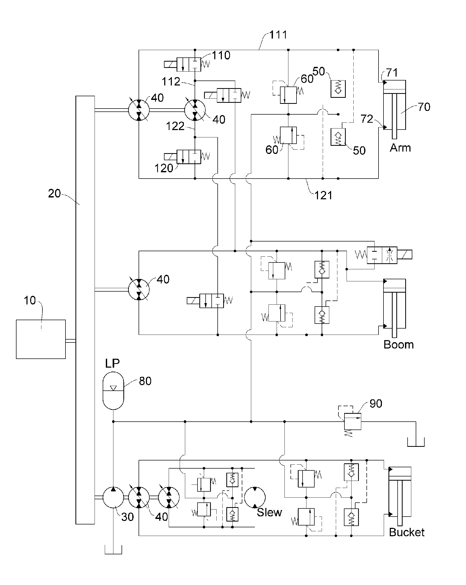
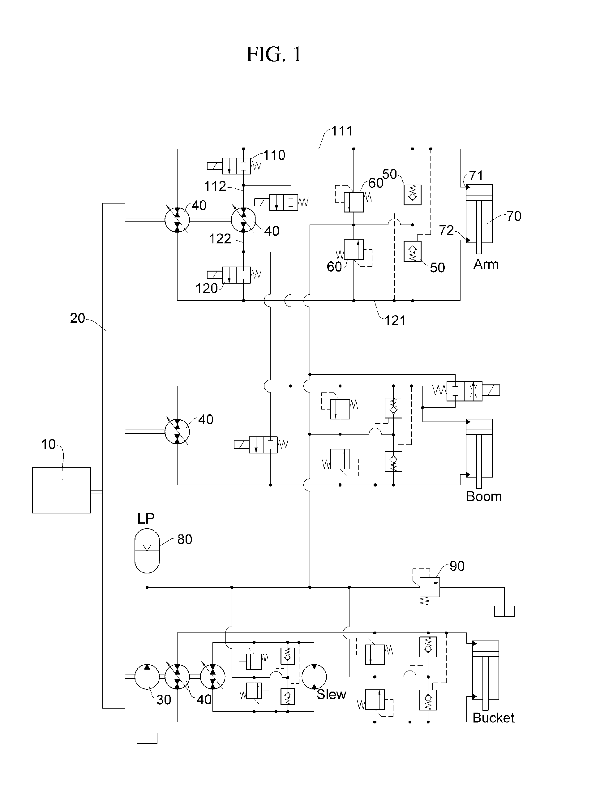
[0018]In the hydraulic system for construction equipment according to the exemplary embodiment of the present disclosure configured as described above, a main cause of pressure loss of a working fluid is removed by excluding a main control valve, which is provided in the hydraulic system in the related art, thereby improving fuel efficiency.
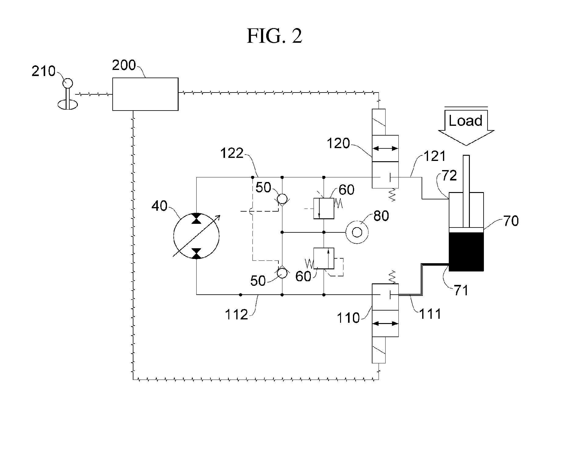
[0019]Further, the hydraulic system for construction equipment according to the exemplary embodiment of the present disclosure includes the logic valves in the first and second hydraulic lines provided to the actuator, respectively, and when it is desired to operate the actuator in a state where an operation of the actuator is stopped by a closing of the logic valves, a pressure difference may be resolved by increasing pressure in sections of the pump / motor and the logic valves in advance even if a load is applied to the actuator, and thus the actuator may implement a desired operation without being affected by the load. That is, it is possible to improve operation controllability of the actuator.

Problems solved by technology

That is, the pressure of the working fluid discharged from the main control valve is inevitably lost while the working fluid passes through the main control valve and various valves, such that energy efficiency is low.

Method used


Image

  • Hydraulic system for construction equipment
  • Hydraulic system for construction equipment
  • Hydraulic system for construction equipment

Examples


Embodiment Construction

[0024]Advantages and characteristics of the present disclosure, and a method of achieving the advantages and characteristics will be clear with reference to an exemplary embodiment described in detail together with the accompanying drawings.

[0025]Hereinafter, an exemplary embodiment of the present disclosure will be described in detail with reference to the accompanying drawings. It should be appreciated that the exemplary embodiment, which will be described below, is illustratively described for helping the understanding of the present disclosure, and the present disclosure may be modified to be variously carried out differently from the exemplary embodiment described herein. In the following description of the present disclosure, a detailed description and a detailed illustration of known configurations or functions incorporated herein will be omitted when it is determined that the detailed description may make the subject matter of the present disclosure unclear. Further, in orde...


PUM


Abstract

The present disclosure relates to a hydraulic system for construction equipment, and more particularly, to a hydraulic system, in which an actuator is controlled by a pump/motor. The hydraulic system for construction equipment according to the present disclosure includes logic valves in first and second hydraulic lines provided to an actuator, respectively, and when it is desired to operate the actuator in a state where an operation of the actuator is stopped by closing the logic valves, a pressure difference may be resolved by increasing pressure in sections of a pump/motor and the logic valves in advance even if a load is applied to the actuator, and thus the actuator may implement a desired operation without being affected by the load. That is, it is possible to improve operation controllability of the actuator.

Description

FIELD OF THE DISCLOSURE[0001]The present disclosure relates to a hydraulic system for construction equipment, and more particularly, to a hydraulic system, in which an actuator is controlled by a pump / motor.BACKGROUND OF THE DISCLOSURE[0002]In general, a hydraulic system for construction equipment includes an engine generating power, a main hydraulic pump driven by receiving the power of the engine to discharge a working fluid, a plurality of actuators performing an operation, an operating unit operated to actuate the actuator of a desired operating device, and a main control valve distributing the working fluid required by the operation of the operating unit to a corresponding actuator.[0003]In the operating unit, a requirement command is formed according to an operation displacement operated by an operator, and a flow quantity of working fluid discharged from the hydraulic pump is controlled by the requirement command. The operating unit may be, for example, a joystick and a pedal...

Claims


Application Information

Patent Timeline
Patent Type & Authority Applications(United States)
IPC IPC(8): F15B11/10F15B13/042
CPCF15B13/042F15B11/10E02F9/2217E02F9/2228E02F9/2289E02F9/2292E02F9/2296F15B7/006F15B11/17F15B21/14F15B2211/20523F15B2211/20546F15B2211/20561F15B2211/20569F15B2211/20576F15B2211/27F15B2211/30515F15B2211/3057F15B2211/30595F15B2211/31529F15B2211/327F15B2211/613F15B2211/625F15B2211/6346F15B2211/7142F15B2211/88
Inventor AN, MIN HA
Owner DOOSAN INFRACORE CO LTD
Why Eureka
Try Eureka