Solar cell

a solar cell and cell technology, applied in the field of solar cells, to achieve the effect of reducing process efficiency and increasing process steps

Inactive Publication Date: 2016-04-14
LG INNOTEK CO LTD
View PDF3 Cites 6 Cited by
  • Summary
  • Abstract
  • Description
  • Claims
  • Application Information

AI Technical Summary

Benefits of technology

[0011]In the solar cell according to the first embodiment, the fourth through holes are inclined by a predetermined inclination angle with respect to the top surface of the support substrate.
[0012]According to the related art, the fourth through holes are formed perpendicular to a top surface of the support substrate like the first to third through holes. In this case, the fourth through holes are formed through a laser etching or the fourth through holes are formed by performing a mechanical etching using a needle after performing the laser etching.
[0013]However, if the laser etching or the laser etching and mechanical etching are performed according to the related art, the front electrode layer may be melted due to high energy of laser, so the front electrode layer may come into contact with the back electrode layer disposed under the front electrode layer, thereby causing the short. In addition, if the fourth through holes are formed by the primary and secondary etchings, the process step may be increased, so the process efficiency may be lowered.
[0014]For this reason, according to the solar cell of the first embodiment, inner surfaces of the fourth holes are inclined when the fourth holes are formed.
[0015]Therefore, a spacing distance between the front electrode layer and the back electrode layer may be increased, so that the front electrode layer may not come into contact with the back electrode layer even if the front electrode layer is partially melted due to the high energy of laser, thereby preventing the short between the front electrode layer and the back electrode layer.
[0016]In the solar cell according to the second embodiment, the fourth through holes include first surfaces perpendicular to the top surface of the support substrate and second surfaces inclined by a predetermined inclination angle with respect to the top surface of the support substrate.

Problems solved by technology

However, in the case of the laser etching, the front electrode layer may be melted due to high energy of laser, so the front electrode layer may come into contact with the back electrode layer, thereby causing the short.

Method used


Image

  • Solar cell
  • Solar cell
  • Solar cell

Examples


first embodiment

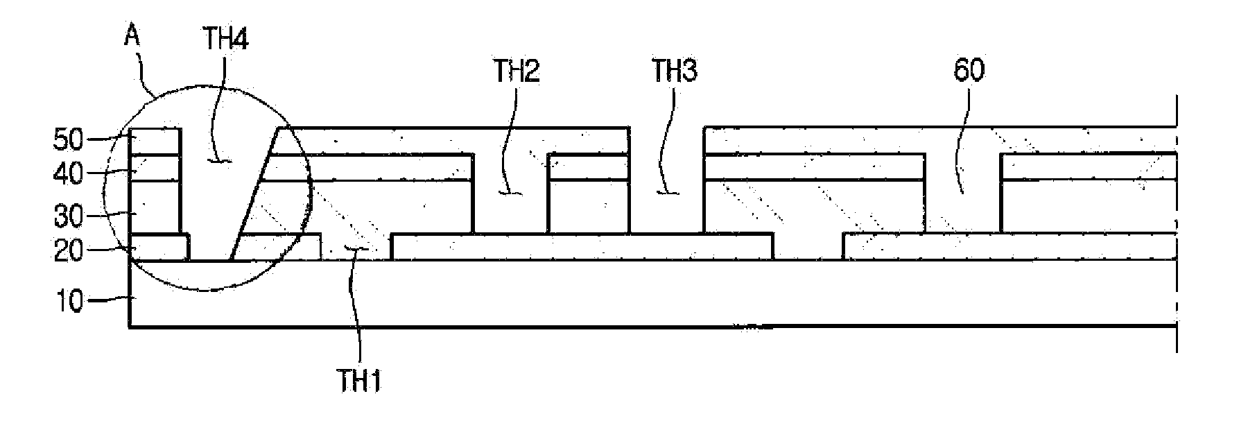
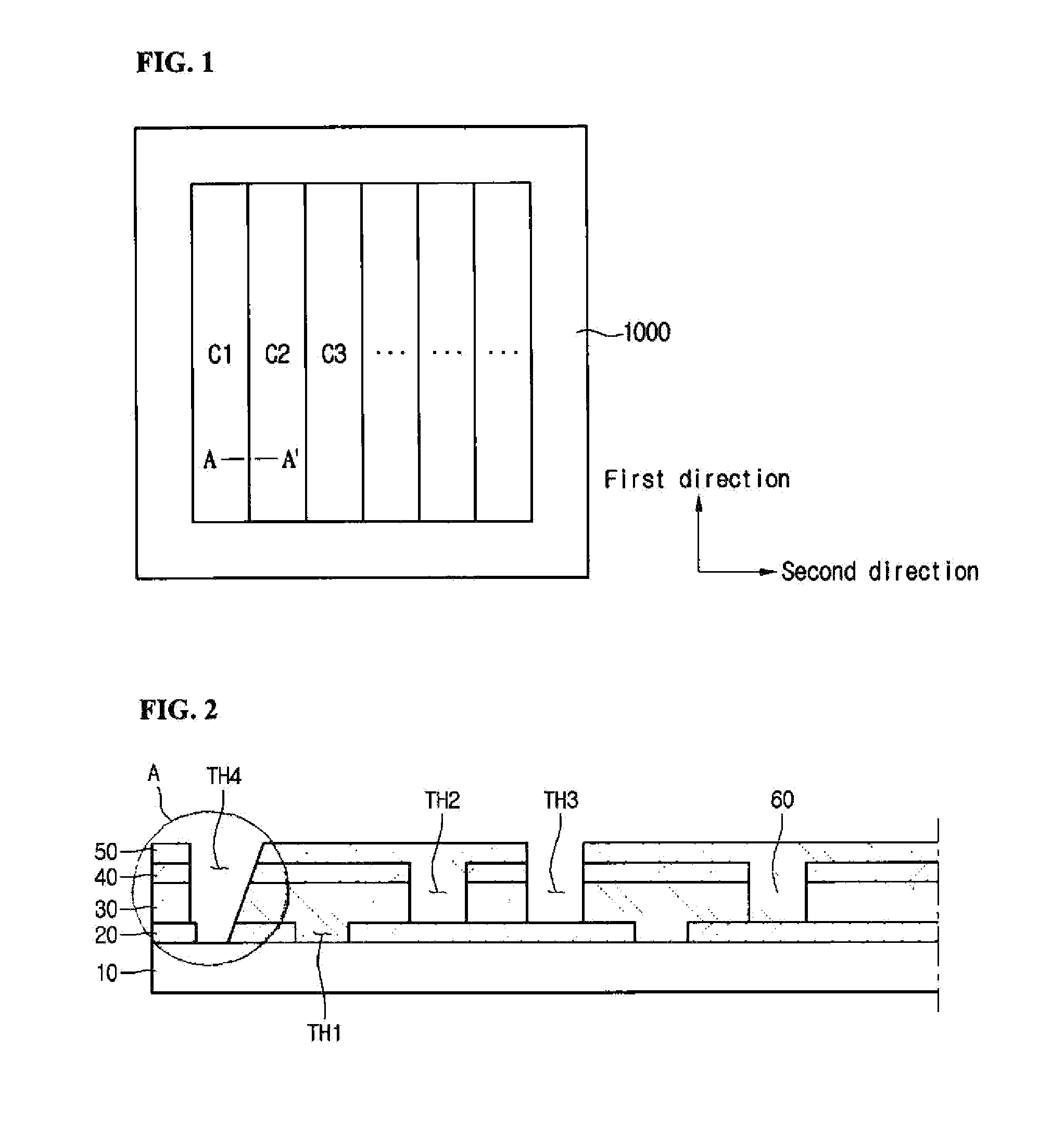
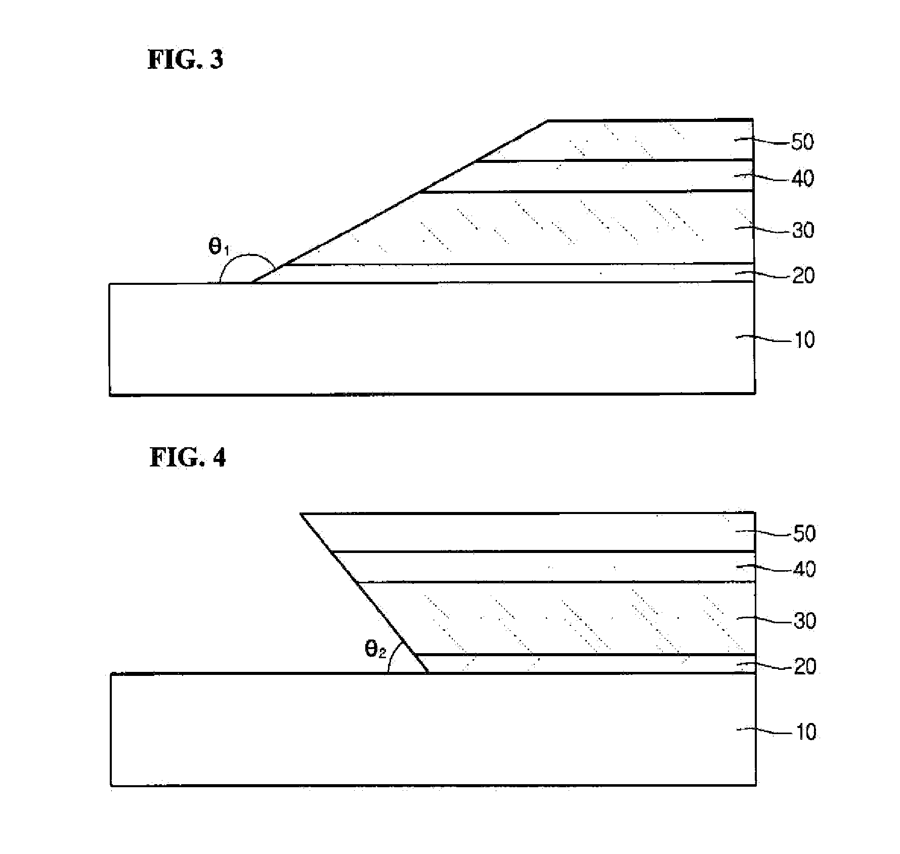
[0030]Referring to FIGS. 1 to 4, the solar cell may include a support substrate 10, a back electrode layer 20, a light absorbing layer 30, a buffer layer 40, a front electrode layer 50 and a plurality of connection parts 60.

[0031]The support substrate 10 has a plate shape, and supports the back electrode layer 20, the light absorbing layer 30, the buffer layer 40, the front electrode layer 50 and the connection parts 60.

[0032]The support substrate 10 may include an insulator. The support substrate 10 may be a glass substrate, a plastic substrate, or a metal substrate. In detail, the support substrate 10 may include soda lime glass. The support substrate 10 may be transparent. The support substrate 10 may be flexible or rigid.

[0033]The back electrode layer 20 may be provided on the support substrate 10. The back electrode layer 20 may be a conductive layer. For example, the back electrode layer 20 may include a metal, such as molybdenum (Mo).

[0034]In addition, the back electrode lay...

second embodiment

[0072]Referring to FIGS. 5 and 6, the solar cell may include a support substrate 100, a back electrode layer 200, a light absorbing layer 300, a buffer layer 400, a front electrode layer 500 and a plurality of connection parts 600.

[0073]In addition, the solar cell according to the second embodiment includes first through holes TH1 formed through the back electrode layer, second through holes TH2 formed through the light absorbing layer, third through holes TH3 formed through the light absorbing layer and the front electrode layer and fourth through holes TH4 formed through the back electrode layer, the light absorbing layer and the front electrode layer.

[0074]The support substrate 100, the back electrode layer 200, the light absorbing layer 300, the buffer layer 400, the front electrode layer 500, the connection parts 600, and the first to third through holes are identical to those of the solar cell according to the first embodiment, so detailed description thereof will be omitted....


PUM


Abstract

A solar cell includes a support substrate; a back electrode layer on the a support substrate; a light absorbing layer on the back electrode layer; a buffer layer on the light absorbing layer; a front electrode layer on the buffer layer; and a fourth through hole formed through the back electrode layer, the light absorbing layer, the buffer layer and the front electrode layer, wherein at least a portion of the fourth through hole is inclined with respect to a top surface of the support substrate.

Description

TECHNICAL FIELD[0001]The embodiment relates to a solar cell.BACKGROUND ART[0002]Recently, concerns about the environmental pollution and depletion of natural resources have been increased, so a solar cell is spotlighted as an alternative energy source having high energy efficiency without the problem of environmental pollution. The solar cell is classified into a silicon semiconductor solar cell, a compound semiconductor solar cell, and a stack-type solar cell depending on the composition of the solar cell. A solar cell including a CIGS light absorbing layer according to the embodiment may belong to the compound semiconductor solar cell.[0003]The CIGS, which is a group I-III-VI compound semiconductor, has a direct transition energy bandgap of 1 eV or more as well as the highest light absorbing coefficient among the semiconductors. The CIGS has very stable electro-optic characteristics, so the CIGS is an ideal material for a light absorbing layer of the solar cell.[0004]The solar cel...

Claims


Application Information

Patent Timeline
Patent Type & Authority Applications(United States)
IPC IPC(8): H01L31/0224
CPCH01L31/022425H01L31/0463Y02E10/50H01L31/04
Inventor JEONG, JONG SEON
Owner LG INNOTEK CO LTD
Why Eureka
Try Eureka