
Magnetic bearing assembly having inner ventilation

Active Publication Date: 2016-04-21
NUOVO PIGNONE TECH SRL
View PDF1 Cites 6 Cited by
  • Summary
  • Abstract
  • Description
  • Claims
  • Application Information

AI Technical Summary

Benefits of technology

The present invention is about an axial magnetic bearing assembly that includes a cooling system to prevent overheating. The cooling system has easy-to-manufacture flow channels that improve the cooling of the magnetic bearing. Overall, this invention makes it easier to cool the magnetic bearing and keeps it running smoothly.

Problems solved by technology

However, such flow is dependant of the friction between two components and the rotational speed of the rotor, and is thus not reliable.
Furthermore, because of uncertainty in the pressure distribution, a back flow could appear which would lead to a lack of radial flow of fluid.
Current axial magnetic bearings do not provide enough inner ventilation, so that the flow of fluid becomes insufficient to cool the axial magnetic bearing.

Method used


Image

  • Magnetic bearing assembly having inner ventilation
  • Magnetic bearing assembly having inner ventilation
  • Magnetic bearing assembly having inner ventilation

Examples


Embodiment Construction

[0029]The following detailed description of the exemplary embodiments refers to the accompanying drawings. The same reference numbers in different drawings identify the same or similar elements. Additionally, the drawings are not necessarily drawn to scale.

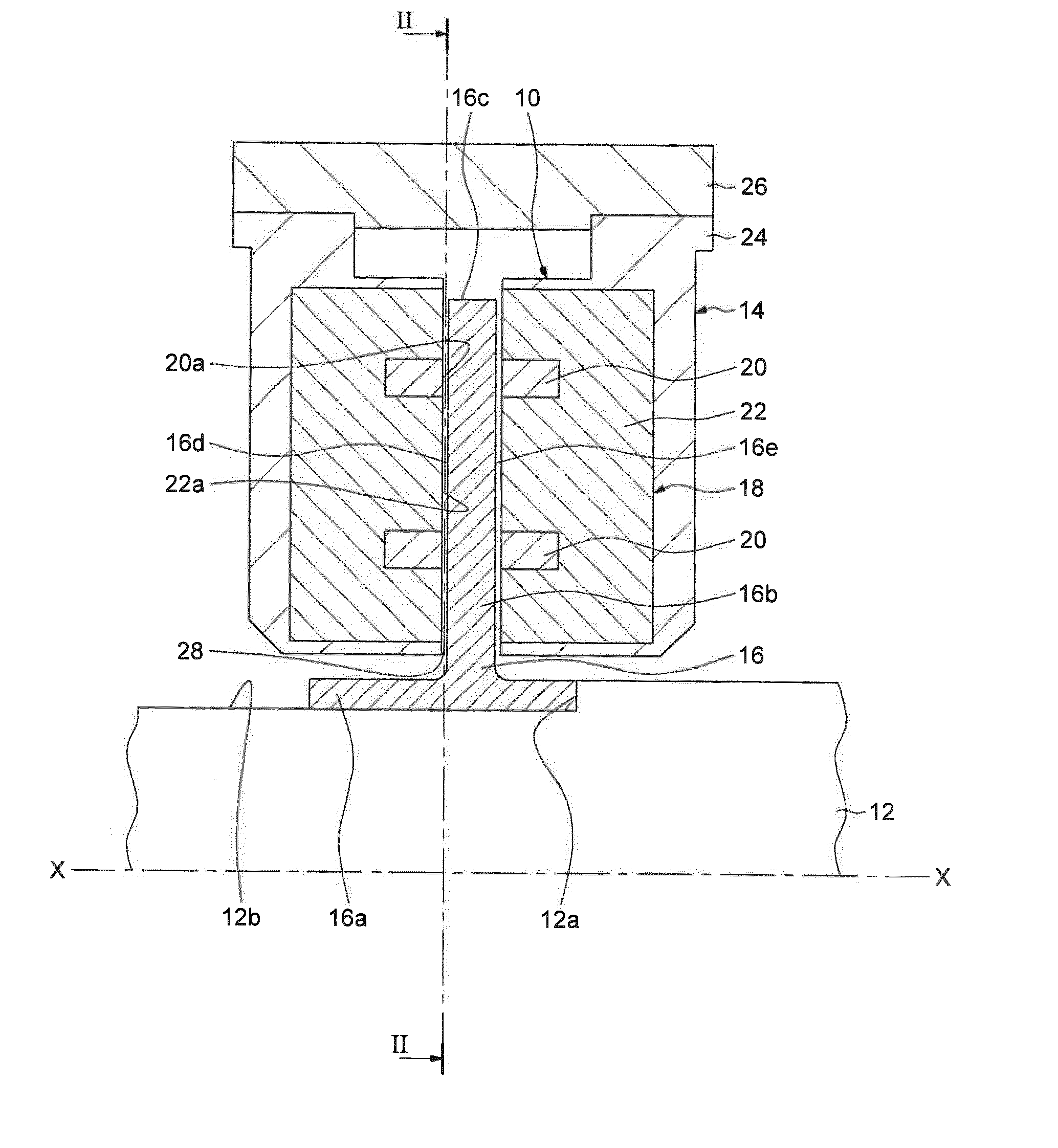
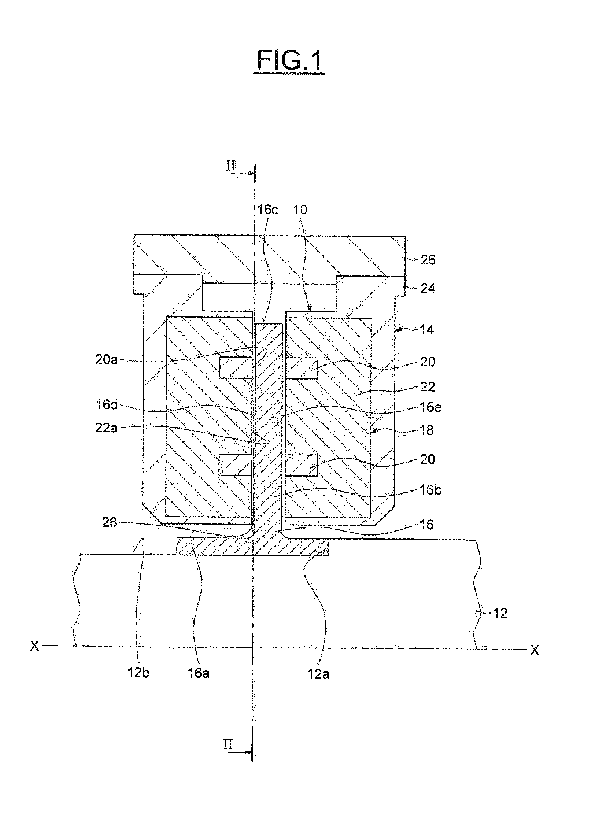
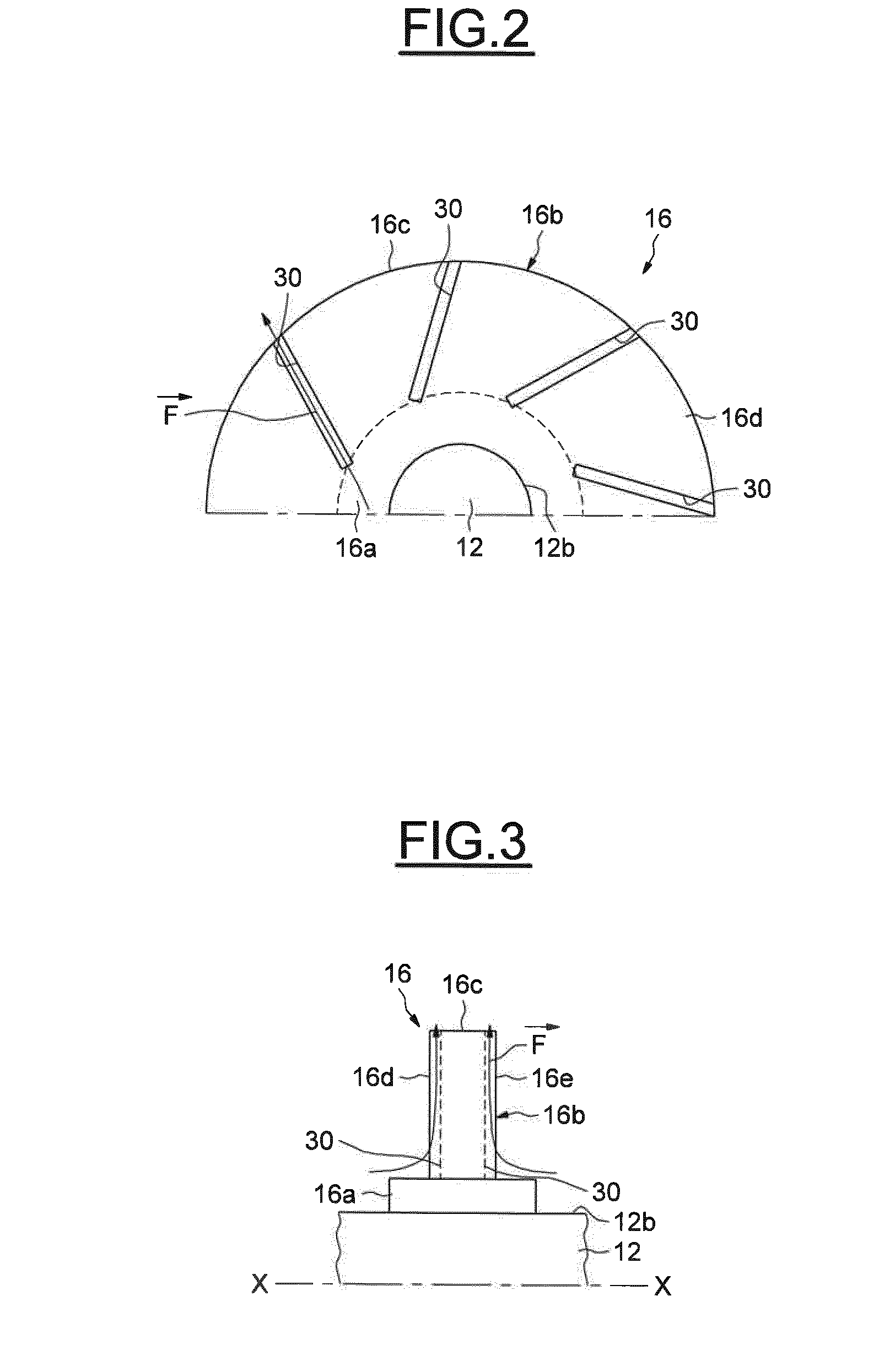
[0030]As illustrated on FIG. 1, a magnetic bearing, designed by general reference number 10, is designed to be mounted in a rotary machine (not shown) comprising a casing or housing, a rotating shaft 12 extending along an axis X-X and adapted to support a rotor part (not shown). For example, if the rotating machine is a centrifugal compressor, the rotor part comprises impellers. The rotating shaft 12 and the associated rotor part form a rotor assembly.

[0031]As illustrated on FIG. 1, the magnetic bearing 10 is of the axial type and is designed to support the rotor shaft 12 inside the stator casing. A radial type magnetic bearing (not shown) may also be associated to the axial magnetic bearing 10 to support the rotating shaft 12.

[00...


PUM


Abstract

A magnetic bearing assembly for a rotary machine having a rotor shaft, comprising a stator magnetic circuit secured to a stationary support element and comprising at least one body of ferromagnetic material and at least one coil, both being fitted in a protective annular housing leaving uncovered a surface of revolution of said ferromagnetic body and a surface of revolution of said one coil, the magnetic bearing assembly comprising an annular thrust collar secured to the rotor shaft and radially extending towards the stator magnetic circuit by a radial portion, said radial portion facing the uncovered surfaces of said ferromagnetic body and said one coil. The annular thrust collar comprises at least one flow channel.

Description

BACKGROUND[0001]Embodiments of the invention relate to bearings, in particular magnetic bearings used in rotary machines having a rotor.[0002]In particular, embodiments of the present invention relate to axial thrust active magnetic bearings having electromagnetic elements arranged in the radial direction and adapted to cooperate with a thrust collar secured to the rotor.[0003]Axial magnetic bearings use electromagnetic forces pulling in opposition on the thrust collar to maintain relative position of a rotating assembly (rotor) to a stationary component (stator). A thrust collar is generally a flat, solid, ferromagnetic disc secured to the rotor. Disc-shaped electromagnetic elements are located on either side of the thrust collar and bolted to the rotary machine housing, forming the active axial magnetic bearing.[0004]Use of magnetic bearings in rotary machines is becoming more and more widespread, in particular in case of corrosive or hot fluid. The inner ventilation of the magnet...

Claims


Application Information

Patent Timeline
IPC IPC(8): F16C37/00F16C32/04
CPCF16C32/0476F16C37/005F16C32/047F16C32/0468F16C32/04F16C37/00F16C39/06F16C32/0459
Inventor MASSINI, ANDREALOMBARDI, LUCABIGI, MANUELESASSANELLI, GIUSEPPEMEI, LUCIANO
Owner NUOVO PIGNONE TECH SRL
Learn More