Tubular lighting device

a lighting device and tube technology, applied in the direction of semiconductor devices for light sources, point-like light sources, light and heating apparatus, etc., can solve the problems of negatively affecting people exposed to this type of lighting, and achieve the effect of reducing the angular spread of the lens, and improving the ratio between the diffusing portion and the transparant portion

Inactive Publication Date: 2016-04-21
SIGNIFY HLDG BV
View PDF3 Cites 23 Cited by
  • Summary
  • Abstract
  • Description
  • Claims
  • Application Information

AI Technical Summary

Benefits of technology

[0025]According to one embodiment, the lens may be in near proximity to the at least one light source. An advantage with a lens arranged in near proximity, for example in abutment, to the at least one light source more of the light emitted by the at least one light source is refracted by the lens, i.e. the lighting device will increase its efficiency. If the lens is placed away from the lig...

Problems solved by technology

However, the use of light emitting diodes in general lighting is generally associated with problem relating to unsatisfactory illumination distribution, such as uneven light distribution, glaring l...

Method used


Image

  • Tubular lighting device
  • Tubular lighting device
  • Tubular lighting device

Examples


Embodiment Construction

[0036]The present invention will now be described more fully hereinafter with reference to the accompanying drawings, in which preferred embodiments of the invention are shown. This invention may, however, be embodied in many different forms and should not be construed as limited to the embodiments set forth herein; rather, these embodiments are provided for thoroughness and completeness, and fully convey the scope of the invention to the skilled person. Like reference characters refer to like elements throughout.

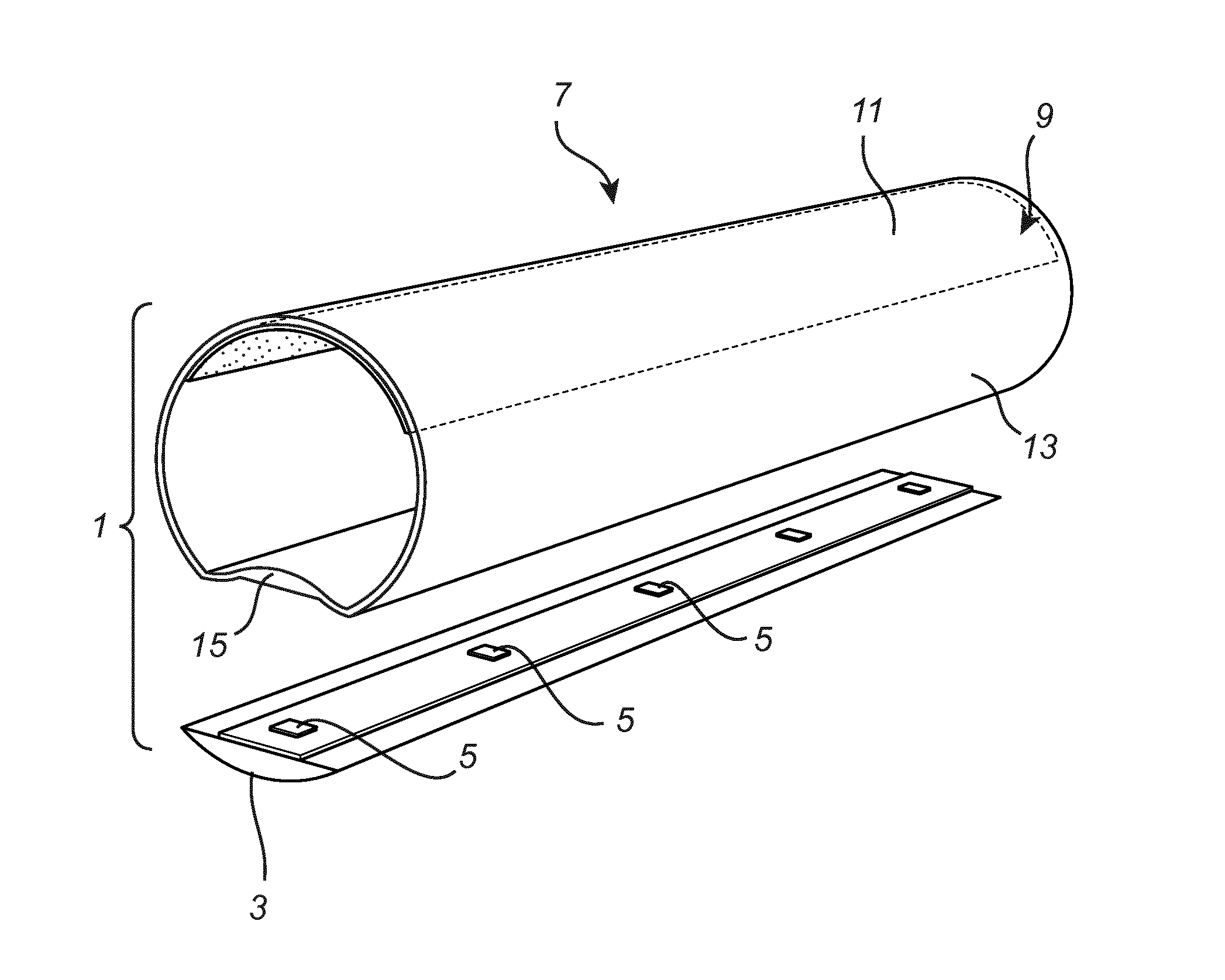
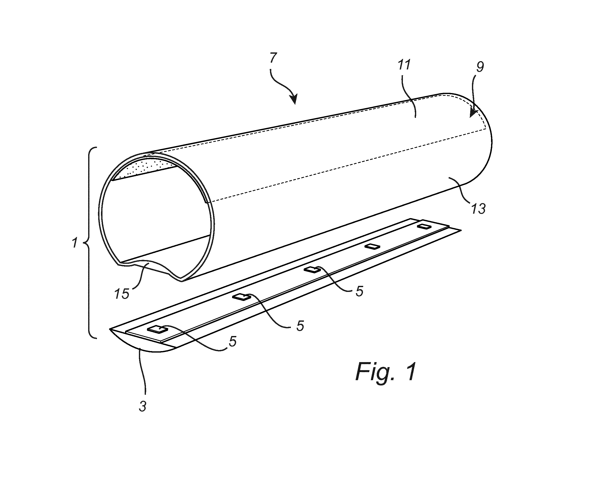
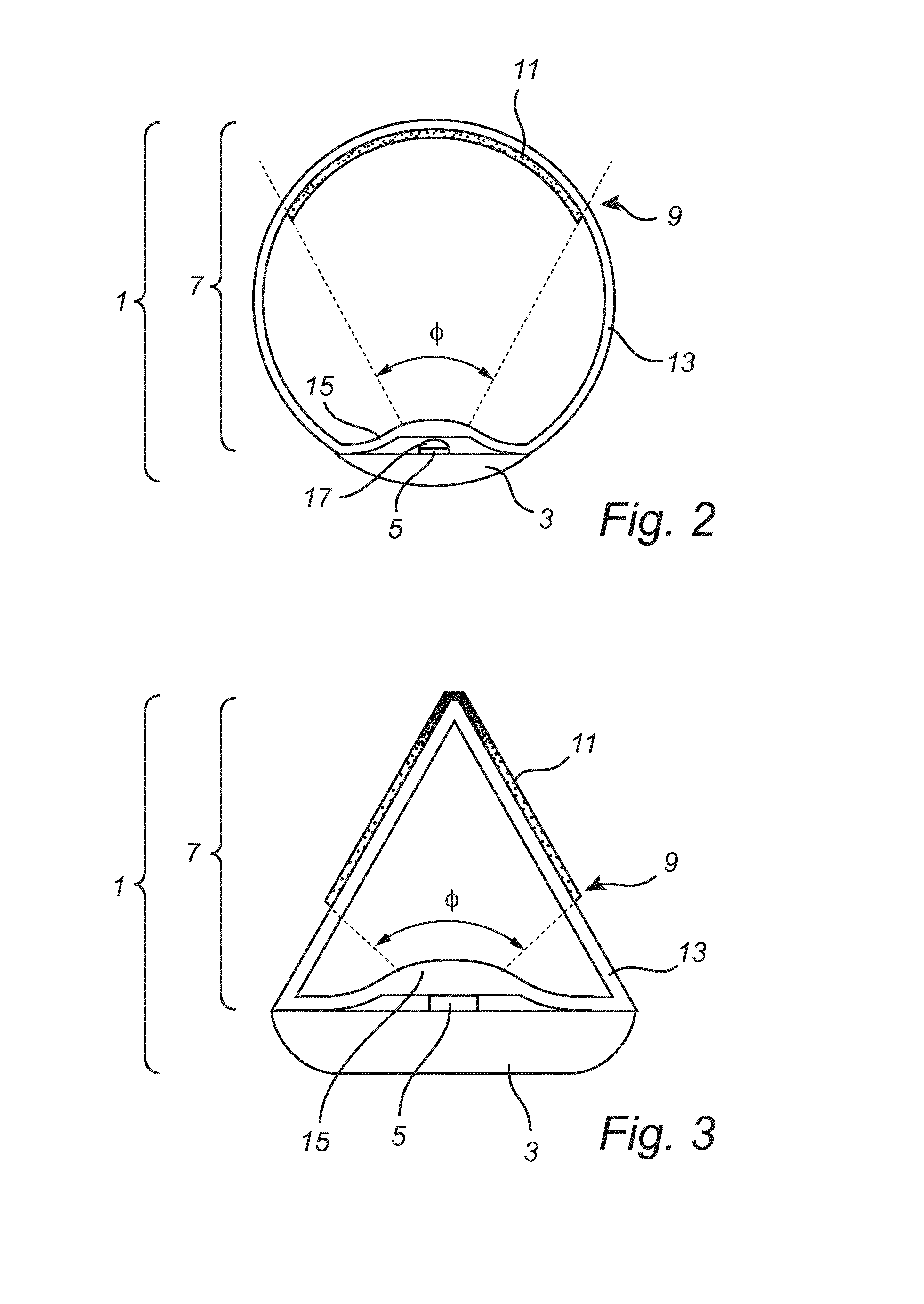
[0037]Referring now to the drawings and to FIG. 1 in particular, there is depicted an exploded perspective view of the tubular lighting device 1 comprising a heat sink 3 and a hollow tubular member 7. As is illustrated in FIG. 1, at least one light emitting diode 5, here five light emitting diodes are mounted with a PCB on the heat sink 3. The periphery of the hollow tubular member 7 includes an elongated lens 15 and a light exit surface 9. The light exit surface 9 and the ...


PUM


Abstract

A tubular lighting device comprising an elongated heat sink (3), at least one light source (5) mounted on the elongated heat sink (3), and an elongated hollow tubular member (7) with a first and a second end arranged along the elongated heat sink (3). The tubular member (7) comprises a lens (15) and a light exit surface (9). The light exit surface is located in front of the lens (15) and the light exit surface (9) have at least one diffusing portion (11) with a transparent portion on each side of each diffusing portion. The at least one diffusing portion (11) covers an area on the light exit surface (9) corresponding to a light distribution of said lens (15) projected on the light exit surface (9), such that all light is directed by said lens (15) onto the at least one diffusing portion (11).

Description

FIELD OF THE INVENTION[0001]The present invention generally relates to a tubular lighting device, and more specifically to a tubular lighting device with improved illumination features for retrofit fluorescent lamp fixtures.BACKGROUND OF THE INVENTION[0002]Today, the interest in developing and improving alternative lighting devices has greatly increased due to the removal of incandescent light bulbs on the market. This has further lead to increased demands on reduced production costs and to increase the performance of the alternative lighting devices. For example, lighting devices with light emitting diodes have several advantages compared to other conventional lighting, including for example high energy efficiency, high light output and long service life. Therefore, light emitting devices have also started to be incorporated into tubular lighting devices, replacing the traditional fluorescent tubes commonly found in offices, and other general places.[0003]However, the use of light ...

Claims


Application Information

Patent Timeline
IPC IPC(8): F21K99/00F21V3/04F21V29/70F21V5/04
CPCF21K9/17F21V5/043F21Y2103/003F21V29/70F21Y2101/02F21V3/04F21S4/28F21K9/27F21Y2103/10F21Y2115/10F21K9/66F21K9/69
Inventor BOONEKAMP, ERIK PAULVAN DELDEN, MARTINUS HERMANUS WILHELMUS MARIA
Owner SIGNIFY HLDG BV
Why Eureka
Try Eureka