Voltage detecting apparatus

Active Publication Date: 2016-04-21
HIOKI DENKI KK
View PDF5 Cites 31 Cited by
  • Summary
  • Abstract
  • Description
  • Claims
  • Application Information

AI Technical Summary

Benefits of technology

[0010]Also, the voltage detecting apparatus according to the present invention, the current-to-voltage converter circuit includes an operational amplifier whose first input terminal is set at the reference voltage, whose second input terminal is connected to the detection electrode, which has a feedback circuit connected between the second input terminal and an output terminal, and which converts the detection current flowing in the feedback circuit to the detection voltage signal. By using such configuration, it is possible to sensitively detect the detection current and convert the detection current to the detection voltage signal.
[0011]Also, the voltage detecting apparatus according to the present invention comprises a case which is formed of an insulating material and inside which the detection electrode, the vibrator, the current-to-voltage converter circuit, and the detector circuit are disposed, wherein the detection electrode is disposed on an inner surface of a wall portion, out of a plurality of wall portions that construct the case, whose outer surface is placed in contact with the insulator with the wall portion as the other insulator, and the vibrator is fixed to an inner surface of one wall portion out of the plurality of wall portions and causes the case to vibrate. By using such configuration, it is possible to eradicate the burden of separately placing the detection electrode and the vibrator in contact with the insulator, which makes it possible to perform detection operations of the voltage to be detected more efficiently.
[0012]Also, the voltage detecting apparatus according to the present invention comprises a shield member that covers the detection electrode, the vibrator, the current-to-voltage converter circuit, and the detector circuit. By using such configuration, it is possible to reduce the influence of external disturbances (such as external magnetic fields and external electric fields) on the circuits that construct the voltage detection apparatus, it is possible to detect and output the detection output in a state where external disturbances have much less influence.
[0013]Also, the voltage detecting apparatus according to the present invention that detects a detection voltage generated in a detected object which is covered by an insulator, the voltage detecting apparatus comprises: a detection electrode that is disposed so as to contact the insulator directly, or indirectly via another insulator; an ultrasonic excitation unit that applies a static magnetic field to the detected object and generates an eddy current at an application position of the static magnetic field on the detection object to induce ultrasound in the detected object in a direction that intersects a surface of the application position; a current-to-voltage converter circuit that converts a detection current to a detection voltage signal, the detection current flowing from the detected object via the detection electrode to a reference voltage in a state where the ultrasound is being induc

Problems solved by technology

If the first aperture were covered with an insulator, charge would also theoretically appear on the surface of such insulator due to the influence of the voltage of the measurement surface, but such charge appearing on the surface of the insulator would quickl

Method used


Image

  • Voltage detecting apparatus
  • Voltage detecting apparatus
  • Voltage detecting apparatus

Examples


Embodiment Construction

[0029]Preferred embodiments of a voltage detecting apparatus will now be described with reference to the attached drawings.

[0030]First, the configuration of the voltage detecting apparatus will be described with reference to the drawings.

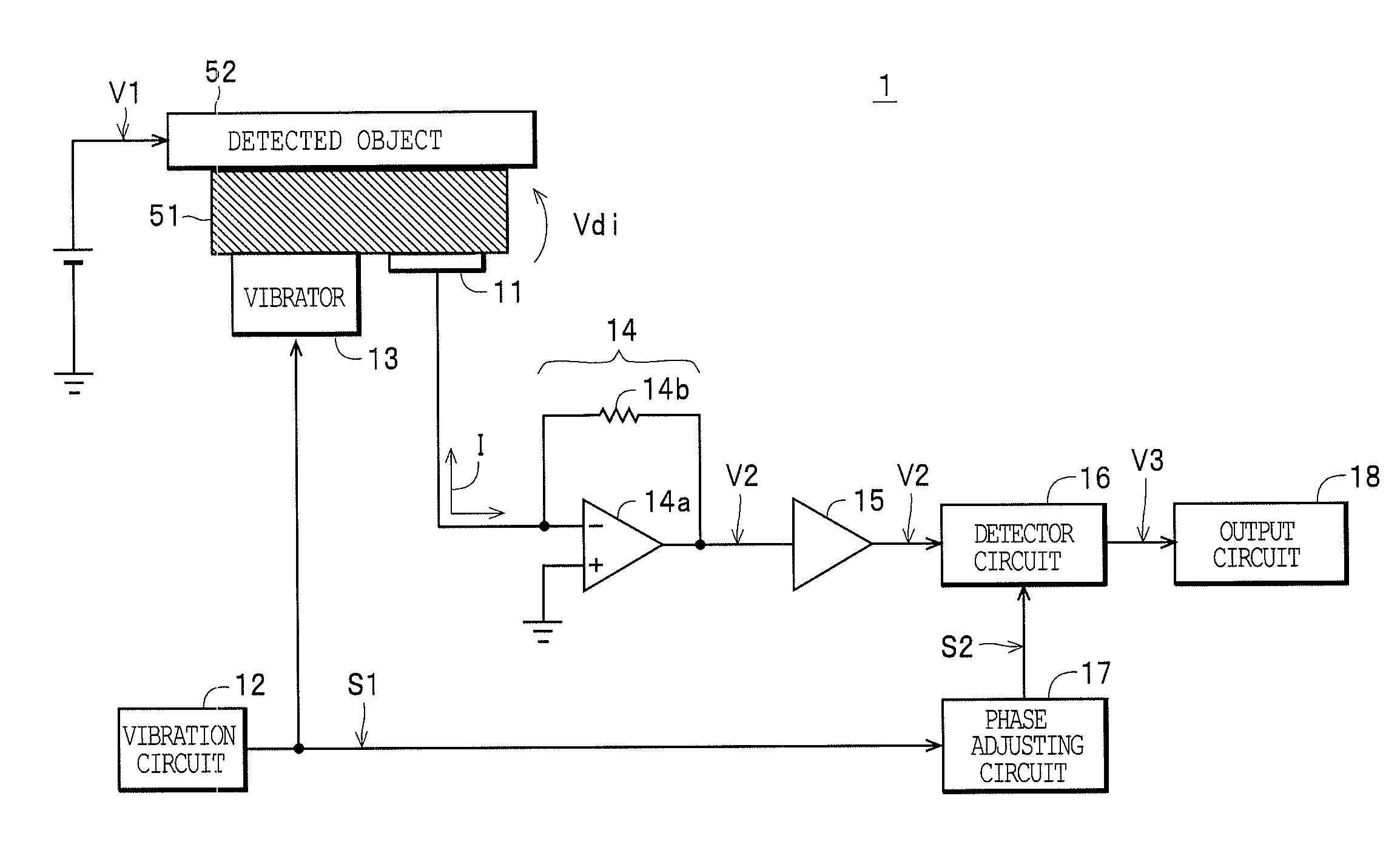
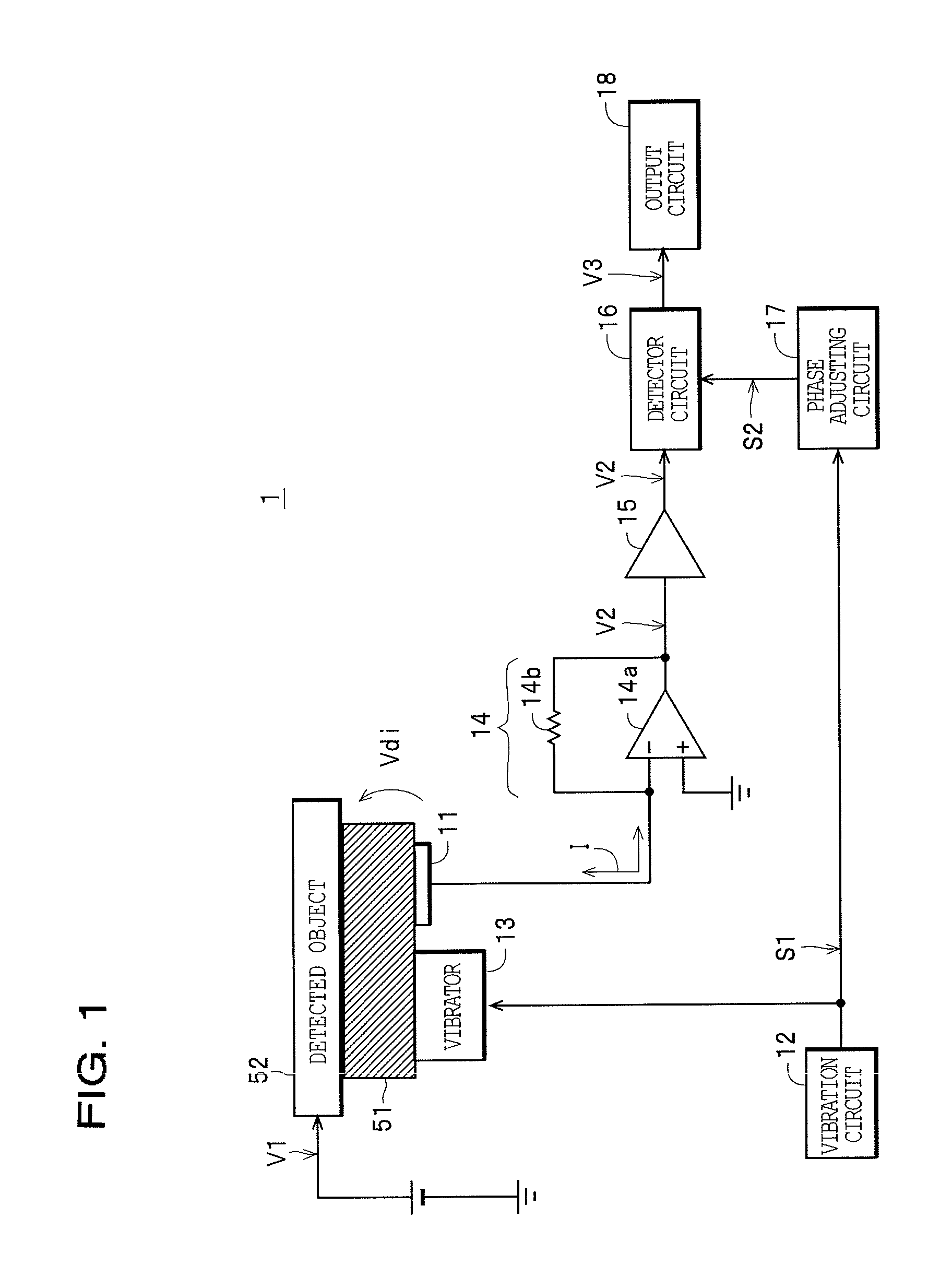
[0031]The voltage detecting apparatus 1 as the voltage detecting apparatus depicted in FIG. 1 is a contactless voltage detecting apparatus and as one example includes a detection electrode 11, a vibration circuit 12, a vibrator 13, a current-to-voltage converter circuit 14, a buffer amplifier 15, a detector circuit 16, a phase adjusting circuit 17, and an output circuit 18, and is configured so as to be capable of contactlessly detecting a voltage (detected voltage) V1 generated in a detected object 52 covered with an insulator 51.

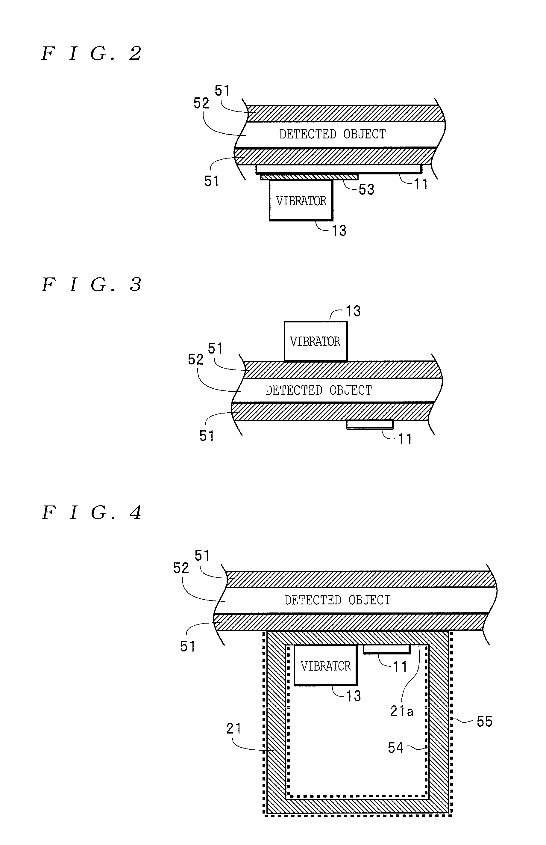
[0032]Here, as depicted in FIG. 1, a position that forms one part of the surface of the detected object 52 may be covered with the insulator 51 or, as depicted in FIGS. 2, 3, and 4, the entire surface may be covered with t...


PUM


Abstract

A voltage detecting apparatus detects a detection voltage generated in a detected object which is covered by an insulator. The voltage detecting apparatus includes: a detection electrode that is disposed so as to contact the insulator directly, or indirectly via another insulator; a vibrator that causes the insulator to vibrate; a current-to-voltage converter circuit that converts a detection current to a detection voltage signal, the detection current flowing from the detected object via the detection electrode to a reference voltage in a state where the insulator is being caused to vibrate, having an amplitude that is modulated in accordance with a potential difference between the detection voltage and the reference voltage, and being synchronized with vibration of the vibrator; and a detector circuit that detects a detection output indicating the potential difference from the detection voltage signal.

Description

1. FIELD OF THE INVENTION[0001]The present invention relates to a contactless voltage detecting apparatus that detects the voltage of a detected object that is covered with an insulating material via the insulating material.2. DESCRIPTION OF THE RELATED ART[0002]As a contactless voltage detecting apparatus, the voltage detecting apparatus (contactless capacitance follower) disclosed in Japanese Examined Patent Application Publication No. H07-92487 is known. This voltage detecting apparatus is equipped with a probe for detecting voltage. The probe includes a detection electrode disposed so as to face a measurement surface (i.e., the surface of the detected object) having a capacitance to be measured, a modulator / driving means that operates in conjunction with the detection electrode to modulate the capacitive coupling between the detection electrode and the measurement surface, and means for defining a path of radiation toward the measurement surface in order to radiate a section of ...

Claims


Application Information

Patent Timeline
IPC IPC(8): G01R15/16G01R19/165
CPCG01R19/165G01R15/16G01R19/0084G01N27/90G01R1/07
Inventor YANAGISAWA, KOICHI
Owner HIOKI DENKI KK
Why Eureka
Try Eureka