
Optical disc medium and optical disc device

a technology of optical discs and optical discs, applied in the field of optical disc media, can solve the problems of large space required for storing such optical discs, and achieve the effects of reducing the influence of user data recording, improving density, and reducing the width of track widths of land or grooves

Active Publication Date: 2016-04-21
PANASONIC INTELLECTUAL PROPERTY MANAGEMENT CO LTD
View PDF0 Cites 2 Cited by
  • Summary
  • Abstract
  • Description
  • Claims
  • Application Information

AI Technical Summary

Benefits of technology

[0005]In a conventional optical disc medium, address information indicating a physical location of storing information in the optical disc medium is recorded by pits or grooves. With the improvement of the recording density of optical disc medium, it is required to develop recording technology of address information which is adapted to the improvement of the recording density. In particular, recording technology of address information enables reduction of influence on recording of user data while ensuring reliability of detection of address information.
[0006]One non-limiting and exemplary embodiment provides an optical disc medium and an optical disc device which achieve high recording density, which ensure reliability of detection of address information, and which reduce influence on recording of user data.
[0011]According to the present disclosure, variation of track width of the land or groove can be reduced. Therefore, an optical disc medium and an optical disc device can be provided, which can ensure reliability of detection of address information and reduce influence on recording of user data while achieving improvement in density.

Problems solved by technology

Therefore, a number of optical discs are required to store significantly large amount of data, and thus, a large space for storing such optical discs is required.

Method used


Image

  • Optical disc medium and optical disc device
  • Optical disc medium and optical disc device
  • Optical disc medium and optical disc device

Examples


first embodiment

[0033]Referring to the drawings, an optical disc medium and an optical disc device according to the present embodiment are described.

1. Optical Disc Medium

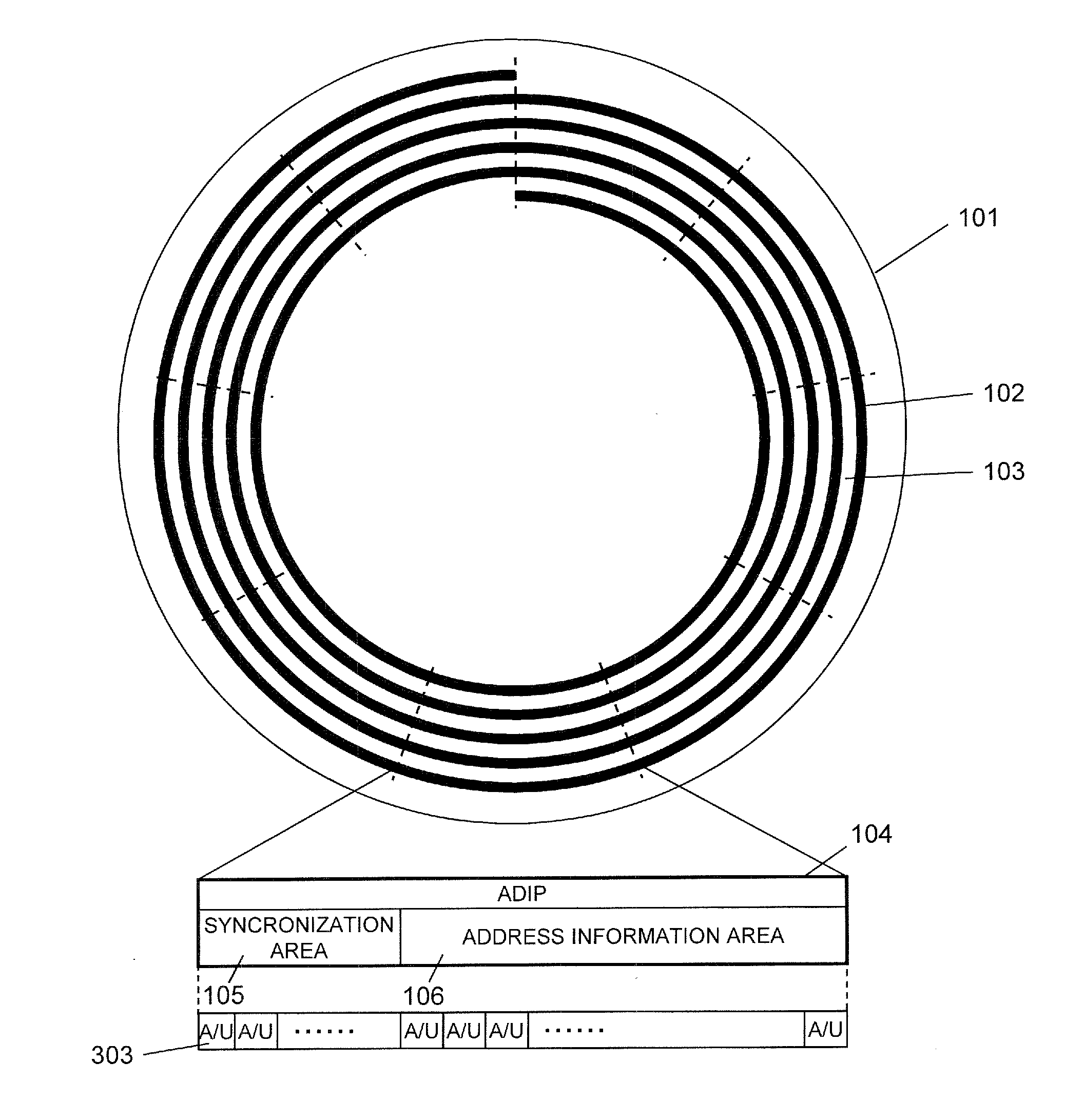
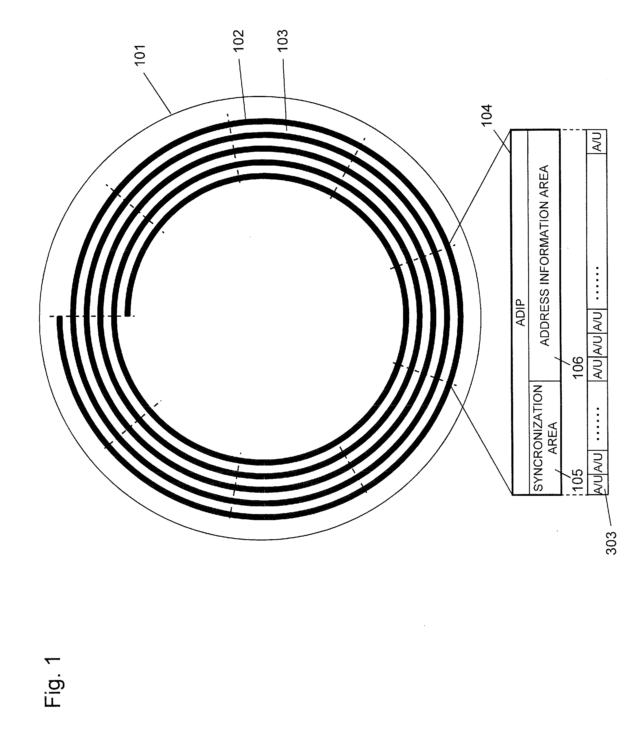
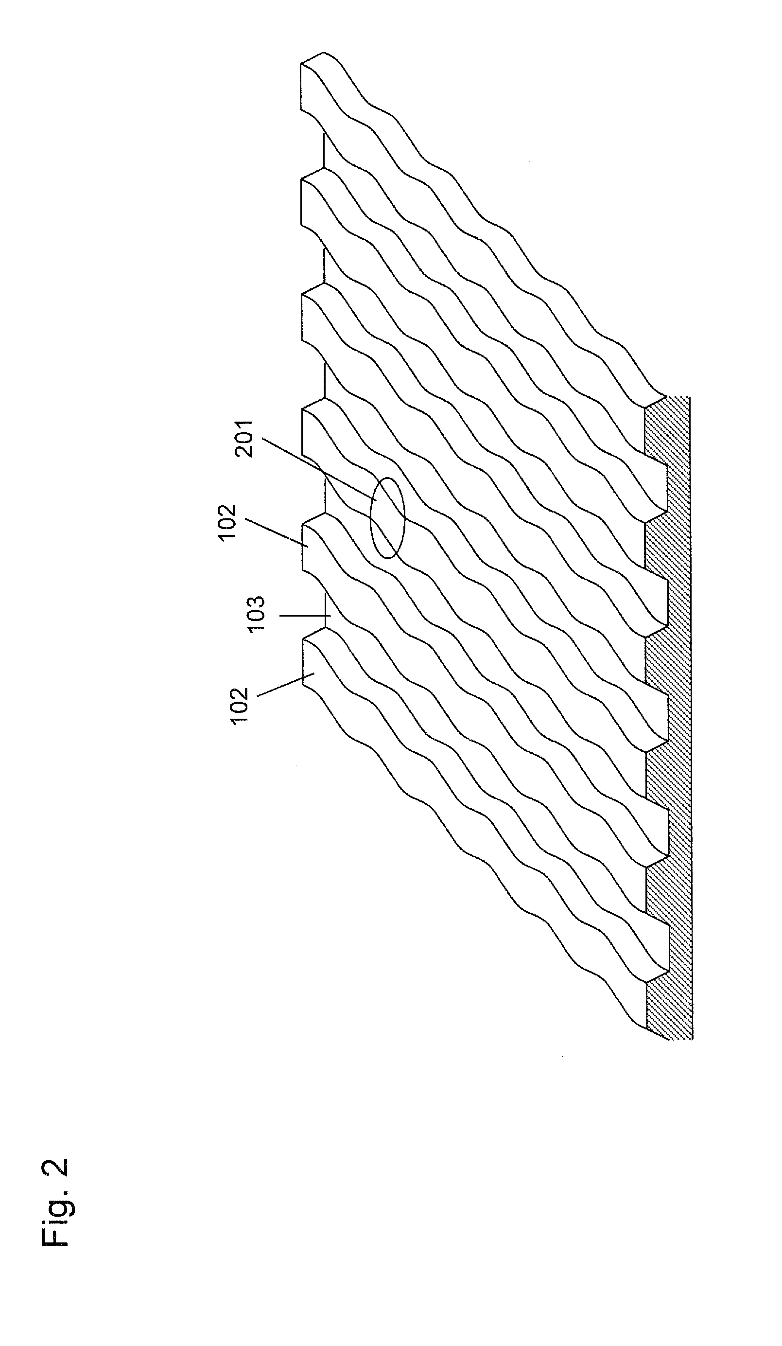
[0034]FIG. 1 is a drawing for describing configuration of tracks of an optical disc medium according to the present embodiment. As shown in FIG. 1, an optical disc 101 has a groove track (hereinafter referred to as “groove”) 102 which is formed in a spiral shape. A land track (hereinafter referred to as “land”) 103 is formed in a spiral shape at a region sandwiched by the groove 102 formed in the spiral shape. The optical disc 101 of the present embodiment can record user data (information) on both of the groove 102 and the land 103. That is, the groove 102 and the land 103 can be used as recording tracks.

[0035]The groove 102 and the land 103 are divided into a plurality of units at a predetermined angle (namely, at a predetermined range of a central angle) in the circumferential direction. Each unit of the divided groove 102 and ...


PUM

PropertyMeasurementUnit
frequencyaaaaaaaaaa
areaaaaaaaaaaa
frequencyaaaaaaaaaa

Abstract

An optical disc medium includes a land and a groove at which information can be recorded. A predetermined number of address information units which record address information of the land or groove are provided in a circumferential direction of the optical disc medium. The address information unit of the land includes three or more address recording areas capable of recording address information. The address information is recorded on one area selected from among the three or more address recording areas. The address information unit of the land has address information which is recorded, in the same modulation, on the side of the inner adjacent groove and on the side of the outer adjacent groove. The one area to be selected from among the three or more address recording areas for recording the address information of the land is different among three address information units adjacently arranged in a radial direction.

Description

BACKGROUND[0001]1. Technical Field[0002]The present disclosure relates to optical disc media on which information can be optically recorded, and to reproduction devices and recording devices therefor.[0003]2. Related Art[0004]In a field of video technology, optical discs such as DVD, BD (Blu-ray (registered trademark) Disc), and the like are well-known. These optical discs are used as media for recording video data and also used as external storage media for personal computers. As external storage media for personal computers, hard disks, flash memories, and the like are also used. Compared with such media, the optical disc media have advantages of long-life, high reliability, and no power necessary for retaining data. In view of the advantages, the optical disc media attract attention as archive media for storing important data, which is managed by data centers and the like. However, even an optical disc BD-XL which is one of the optical discs having the largest storage capacity, h...

Claims


Application Information

Patent Timeline
Patent Type & Authority Applications(United States)
IPC IPC(8): G11B7/007
CPCG11B7/00718G11B2007/00754G11B7/24085G11B7/24079G11B7/007G11B7/0053G11B7/00745G11B7/24082G11B20/10G11B20/1217G11B27/3027
Inventor MINAMINO, JUNICHIMIYASHITA, HARUMITSUNAKATA, KOHEI
Owner PANASONIC INTELLECTUAL PROPERTY MANAGEMENT CO LTD
Learn More