
Methods and systems for target cleaning die surfaces of a die of a press machine

a technology of press machine and die surface, which is applied in the direction of forging/pressing/hammering apparatus, forging/hammering/pressing machines, and shape safety devices, etc., can solve the problems of press machine not being able to operate, workpiece blemishes or defects, and affecting productivity and press machine efficiency

Active Publication Date: 2016-04-28
HONDA MOTOR CO LTD
View PDF6 Cites 29 Cited by
  • Summary
  • Abstract
  • Description
  • Claims
  • Application Information

AI Technical Summary

Benefits of technology

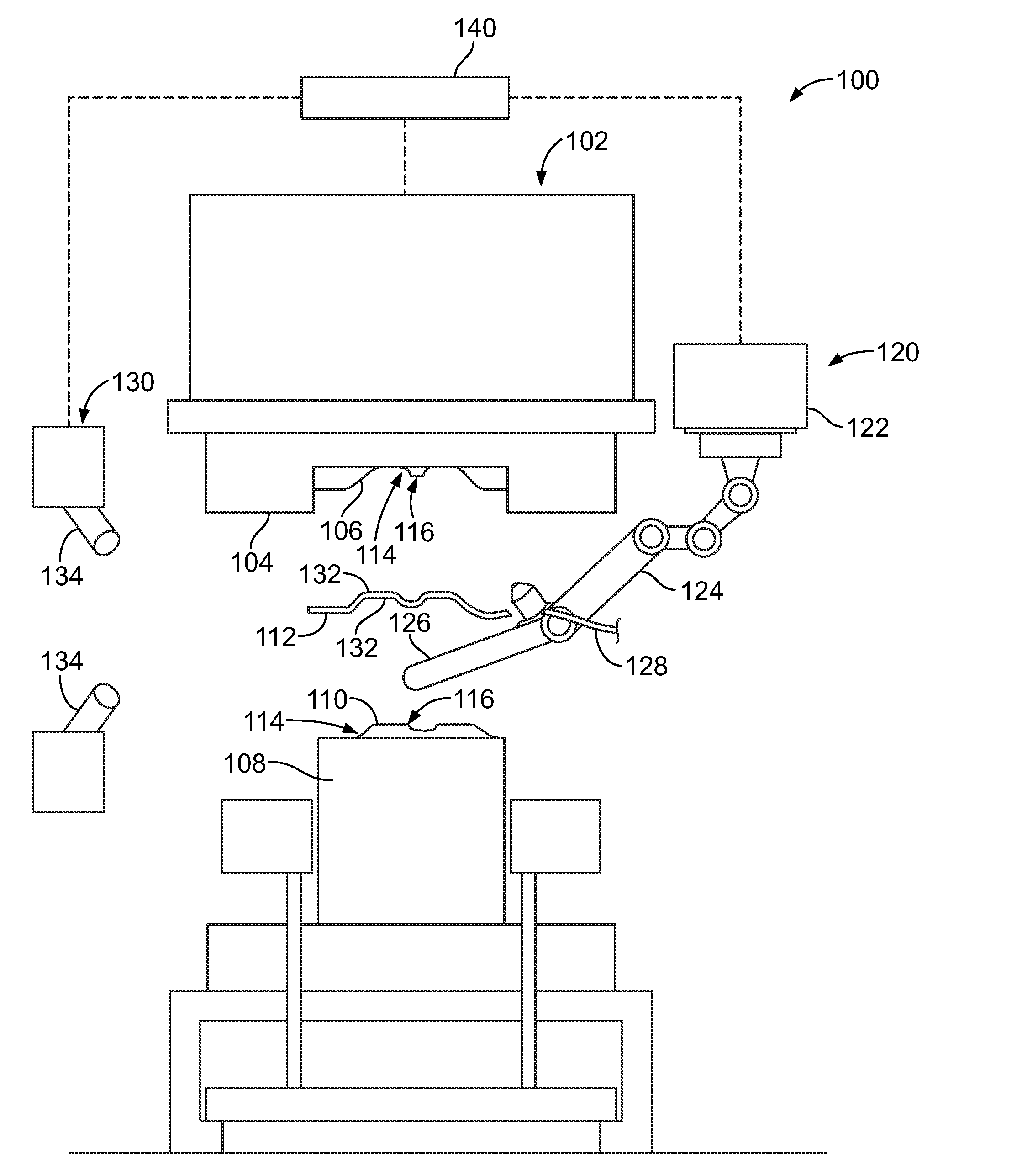
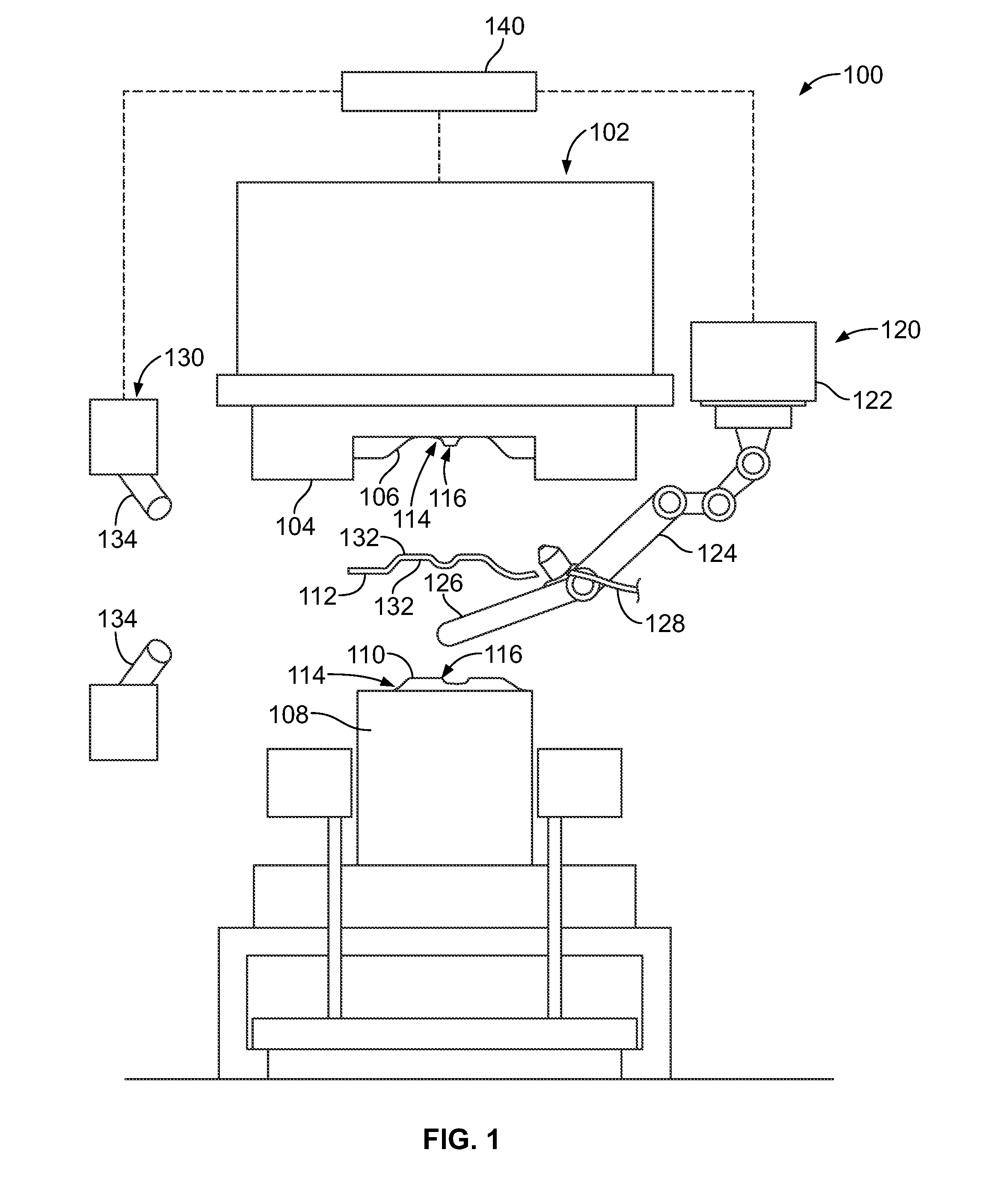
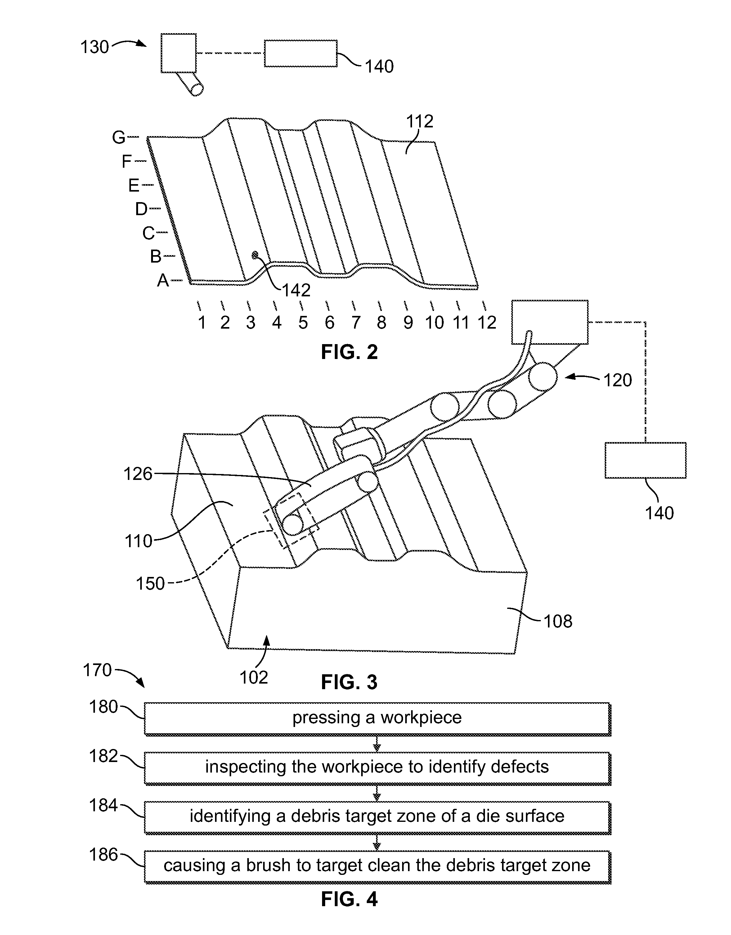
This patent describes a stamping system that includes a press machine and a workpiece surface inspection system for identifying defects in the workpiece after pressing. Additionally, there is a die cleaning machine for removing foreign debris from the press's dies during a cleaning operation. The system also includes a control module that directs the die cleaning machine to target specific areas of the press's dies based on detected defects. Overall, this system improves the efficiency and accuracy of the stamping process.

Problems solved by technology

During a stamping operation, foreign debris or contaminates have the potential to cause blemishes or defects in the workpiece being formed when such foreign debris is trapped between the workpiece and the die surfaces of the die of the press machine.
The press machine is cycle-stopped and the press machine is secured such that the press machine is unable to operate.
Because all of the machines in the area are shut down, productivity and press machine efficiency are negatively affected.
Additionally, any time the operator enters the press machine space, there exists the potential for injury.
Furthermore, frequently, due to their small size, the contaminates are difficult to see and with the current technique of wiping the die surface with a lint-free towel, the contaminates may be moved off of one location on the die surface to another location on the die surface, and are not removed from the die space, thus risking causing further defects.

Method used


Image

  • Methods and systems for target cleaning die surfaces of a die of a press machine
  • Methods and systems for target cleaning die surfaces of a die of a press machine
  • Methods and systems for target cleaning die surfaces of a die of a press machine

Examples


Embodiment Construction

[0012]Various embodiments of methods and systems for cleaning dies of a die of a press machine are provided. It should be noted that although the various embodiments are described in connection with the automotive industry, such as for an automobile assembly process, one or more embodiments may be implemented in different industries and for different applications.

[0013]One or more embodiments include a die cleaning machine used to remove foreign debris from a die surface of an upper die and / or a lower die. The die cleaning machine removes the foreign debris from a targeted area of the die surface, which may be identified by an inspection system that inspects formed workpieces for defects and, based on the location of the defect, the die cleaning machine is able to automatically target the particular area of the die surface having the foreign debris. Removal of such debris is performed by an automated machine as opposed to by a human operator physically wiping the die surface with a ...


PUM

PropertyMeasurementUnit
surface inspectionaaaaaaaaaa
specific areaaaaaaaaaaa
workpiece surface inspectionaaaaaaaaaa

Abstract

A stamping system includes a press machine having installed an upper die with an upper die surface and a lower die with a lower die surface. The upper die surface and the lower die surface each have a non-planar geometry. The press machine presses a workpiece between the upper die surface and the lower die surface during a pressing operation. A die cleaning machine is provided having a brush configured to remove foreign debris from at least one of the upper die surface and the lower die surface during a cleaning operation, wherein the die cleaning machine is configured to maneuver the brush in various orientations relative to the press machine to clean the non-planar upper die surface or the non-planar lower die surface.

Description

BACKGROUND[0001]The present disclosure relates generally to methods and systems for target cleaning die surfaces of a die of a press machine.[0002]During a stamping operation, foreign debris or contaminates have the potential to cause blemishes or defects in the workpiece being formed when such foreign debris is trapped between the workpiece and the die surfaces of the die of the press machine. When the workpiece is identified as having a blemish or defect caused by contaminates on the die surface and negatively affecting its fitness for use, the following steps typically take place to remedy the situation. The press machine is cycle-stopped and the press machine is secured such that the press machine is unable to operate. Safety gates are raised around the area surrounding the press machine. A human operator procures cleaning material, for example a lint-free towel, and then enters the press machine space. The operator attempts to locate the contaminate causing the defect. The oper...

Claims


Application Information

Patent Timeline
Patent Type & Authority Applications(United States)
IPC IPC(8): B21J13/02B08B1/00B21D22/06
CPCB21J13/02B08B1/002B21D22/06B21D22/02B21J13/00B08B15/04B25J9/0018B25J11/00B30B15/0082B08B1/12B21B45/02B08B1/00
Inventor STAATS, DOUGJURICH, MILAN
Owner HONDA MOTOR CO LTD
Learn More