
Desktop open-gantry spect imaging system

a spectroscopic system and desktop technology, applied in the field of design of spectroscopic systems, can solve the problems of low tomographic spatial resolution, high production cost, and difficulty in monitoring objects

Inactive Publication Date: 2016-04-28
PARTO NEGAR PERSIA CO
View PDF4 Cites 4 Cited by
  • Summary
  • Abstract
  • Description
  • Claims
  • Application Information

AI Technical Summary

Benefits of technology

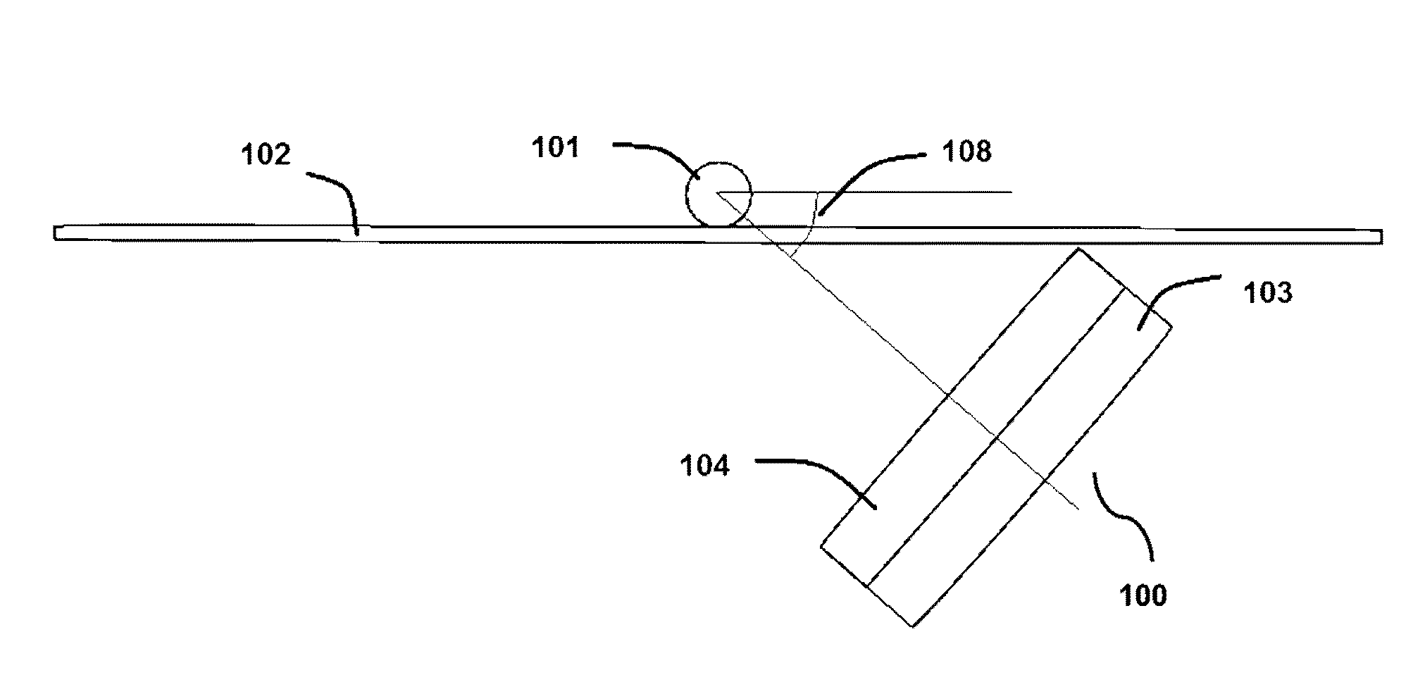
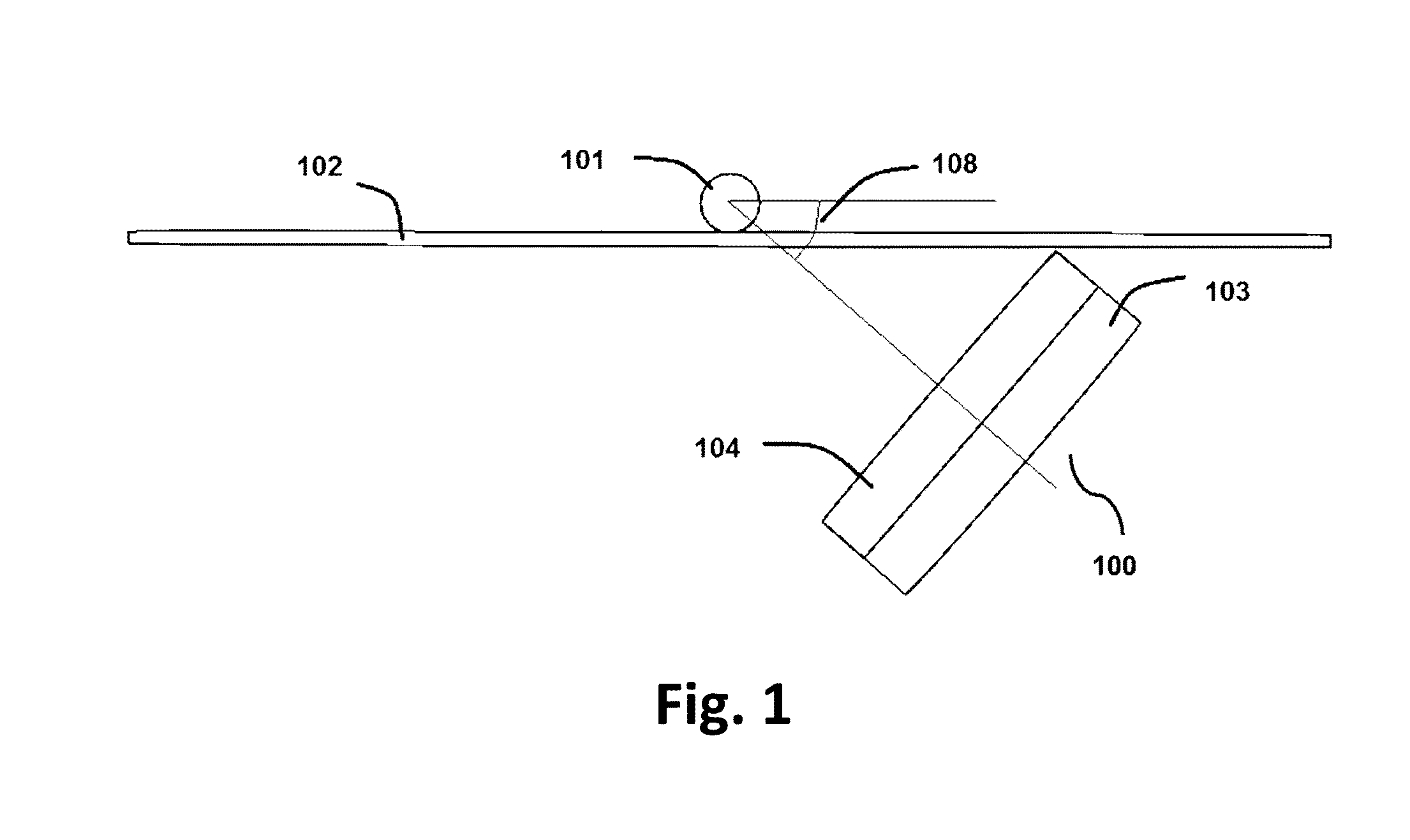
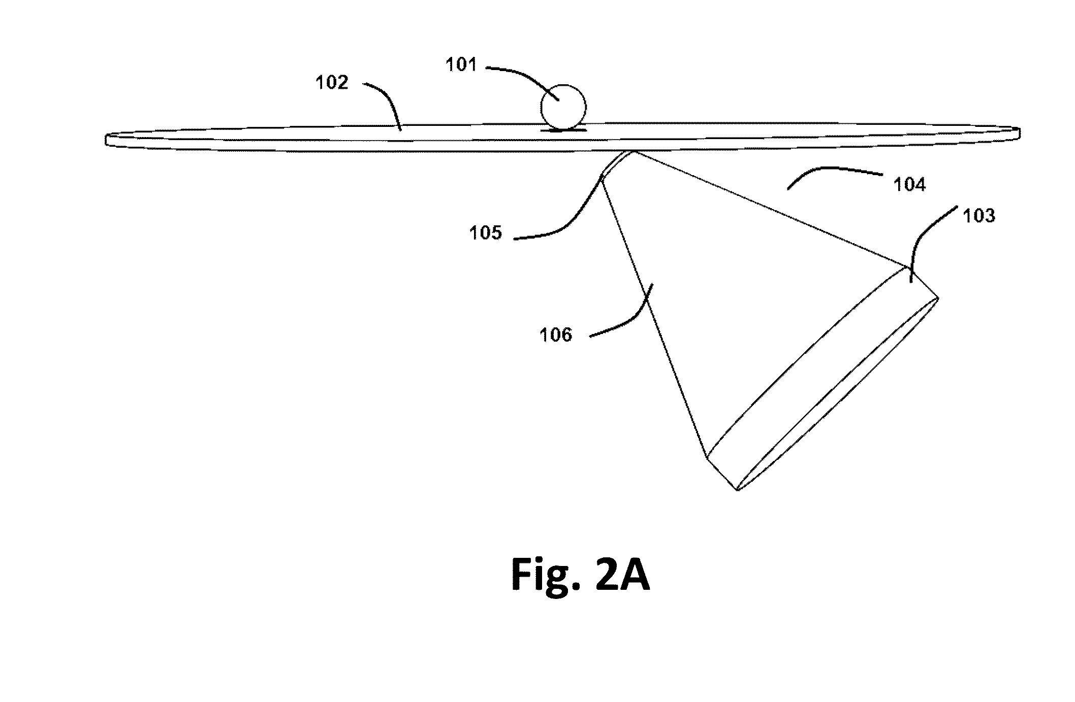
This patent describes a new system for single-photon emission computed tomography (SPECT) imaging. The system has an open-gantry structure and contains an imaging desk and at least one head. The head is located underneath the imaging desk with a tilt angle from the desk. The head rotates around an axis of rotation, which is perpendicular to the desk, for data acquisition. The head contains a collimator and a detector. The system can use different types of collimators and detectors, such as a pinhole collimator or a monolithic scintillation crystal coupled to PMTs. The method for data acquisition involves placing the object to be imaged on the imaging desk, rotating the head around the object while tilting the head underneath the desk, and acquiring some projection views. The technical effect of this patent is the introduction of a new system and method for SPECT imaging with improved sensitivity and accuracy.

Problems solved by technology

Closed gantry of the systems, and difficult monitoring of the object are known drawbacks of the systems disclosed in the prior art.
Moreover, high production cost and low tomographic spatial resolution, are among other negative aspects of SPECT systems reported in prior art.

Method used


Image

  • Desktop open-gantry spect imaging system
  • Desktop open-gantry spect imaging system
  • Desktop open-gantry spect imaging system

Examples


example 1

[0036]In this example, a set of Monte Carlo simulations was performed to assess the influence of tilt angle on image quality. The theoretical range for tilt angle in the application is 0°-90°. At tilt angle of 0°, the head is perpendicular to the imaging desk. In contrast, at 90° tilt angle, the head is parallel to the imaging desk. However, regarding the assumed sizes of the detector and the collimator (detector size of 30 cm (W)×30 cm (L)×⅜″ (thickness), collimator thickness of 5 mm), to locate the head and collimator entirely below the imaging desk, the minimum tilt angle for retaining the head underneath the desk is about 30°. But the tilt angle of 0° and 15° were also simulated for better understanding of the effect of tilt angle on the image quality parameters. Furthermore, at a tilt angle of 90°, all projection views are the same and hence image reconstruction is not possible. So, in the assessment process, tilt angles ranging from 0° to 75° were analyzed. For all assessments...

example 2

[0037]To evaluate the spatial resolution, 6 point sources of Technetium-99m (Tc-99m) were placed at different locations in the FOV, the details of which is presented and set forth in TABLE 2 herein below. It should be noticed that the center of image matrix was considered to be at the origin. Different sources are designated by numbers 1 to 6. All point sources contain the same value of activity. Also, all of them are ideal point sources i.e. they have no dimension.

TABLE 2The positions of the 6 point sources scanned to assess spatial resolution.SourcesCartesian coordinates (in mm)Source #1(0, −5, −5)Source #2(0, 0, −5)Source #3(0, −5, 0)Source #4(0, 0, 0)Source #5(0, −5, 5)Source #6(0, 0, 5)

[0038]Data acquisition was performed using 16 views over 360° span. Each projection view was stored in a 512×512 matrix. Data were then reconstructed with an image voxel size of (0.2 mm)3, using the dedicated image reconstruction code developed for the system via 3 iterations. Gaussian fitting wa...


PUM


Abstract

An open-gantry structure of SPECT imaging system for scanning human small organs or small animals and method for preparing the system is disclosed. The system contains an imaging desk that one or multiple detector heads are rotated around the object to be scanned while tilted under the imaging desk and dedicated image reconstruction algorithm was developed for the system in case of applying single pinhole collimator.

Description

CROSS REFERENCE TO RELATED APPLICATION[0001]This application claims the benefit of priority from U.S. Provisional Patent Application Ser. No. 62 / 146,350, filed on Apr. 12, 2015, and entitled “Desktop Open-Gantry SPECT Imaging System Using Tilted Detector,” which is incorporated by reference herein in its entirety.SPONSORSHIP STATEMENT[0002]This application has been sponsored by the Iranian Nanotechnology Initiative Council, which does not have any rights in this application.TECHNICAL FIELD[0003]The present application generally relates to the design of a SPECT imaging system for scanning small animal and the human organs, and more specifically to the development of a dedicated image reconstruction algorithm to generate 3-dimensional map of activity concentration using acquired projection data.BACKGROUND[0004]Regarding the highlighted role of molecular imaging in pre-clinical imaging, much effort have been devoted to development of high performance single-photon emission computed tom...

Claims


Application Information

Patent Timeline
Patent Type & Authority Applications(United States)
IPC IPC(8): G01T1/166G01T1/20G01T1/202G21K1/02
CPCG01T1/1663G01T1/202G01T1/2006G21K1/02G01T1/1648A61B6/037A61B6/06A61B6/4208A61B6/44A61B6/508
Inventor ZERAATKAR, NAVIDFARAHANI, MOHAMMAD HOSSEINAY, MOHAMMAD REZASARKAR, SAEED
Owner PARTO NEGAR PERSIA CO
Learn More