Capacitive sensing device

a capacitance sensing and capacitance technology, applied in the field of capacitance sensing devices, can solve the problems of increasing noise, increasing the s/n ratio of capacitance to be detected, and remaining unsolved, so as to reduce the variability of the sensed value obtained from one sensing electrode, reduce noise, and reduce noise. the effect of radiated nois

Active Publication Date: 2016-04-28
ALPS ALPINE CO LTD
View PDF11 Cites 18 Cited by
  • Summary
  • Abstract
  • Description
  • Claims
  • Application Information

AI Technical Summary

Benefits of technology

[0028]In the capacitive sensing device of the present invention, a matrix obtained by removing a row and a column in which a sum of codes is greatest from a basic matrix such as the Hadamard matrix is used as the driving matrix. Therefore, a variation in the sensed value obtained from one sensing electrode is reduced such that an amount of a change in capacitance can be detected with high resolution. Further, since the sum of the codes of the driving signal when the driving signal is simultaneously applied to the plurality of driving electrodes can decrease, an increase in radiated noise can be suppressed.
[0029]Further, it is possible to enhance the effect of averaging the noise in the sensed value obtained from one sensing electrode and improve an S / N ratio by replacing the code “0” included in the decoded matrix with “1” or “−1”.

Problems solved by technology

However, in the 1-hot driving scheme, since only information on the capacitance at one intersection is obtained from the sensing electrode when the driving signal is applied to the driving electrode, there is a disadvantage in that influence of noise increases and an S / N ratio of capacitance to be detected increases.
However, in the multi-driving scheme of simultaneously driving a plurality of electrodes, the following problems remain unsolved.
On the other hand, in the multi-driving scheme, when the balance of the sum of the codes of respective rows applied to one sensing electrode (at each time) is greatly changed, the base capacitance is not uniformly cancelled, unlike the 1-hot scheme.
Thus, when the balance of the sum of the codes in each row (at each time) is greatly changed, it is necessary to increase the bit number of the A / D converter, and a circuit cost increases.
However, in a typical ASIC, since the driving signal applied to the driving electrode is a rectangular wave, multiplication frequencies are widely included on a high frequency side even when a driving frequency is 150 kHz or lower, and thus, the multiplication frequencies cannot be avoided from a high frequency band.
Therefore, when a matrix in which a sum of the codes of the row increases is used, radiated noise increases when the driving electrode is driven at a relatively low frequency.
However, in this matrix, since the number of driving electrodes to which the driving signal is applied at a timing of each row is limited to 2, effects of averaging of the noise and reduction of the S / N ratio, which are original purposes of the multi-driving scheme, are somewhat degraded.

Method used


Image

  • Capacitive sensing device
  • Capacitive sensing device
  • Capacitive sensing device

Examples


Embodiment Construction

Configuration of Capacitive Sensing Device

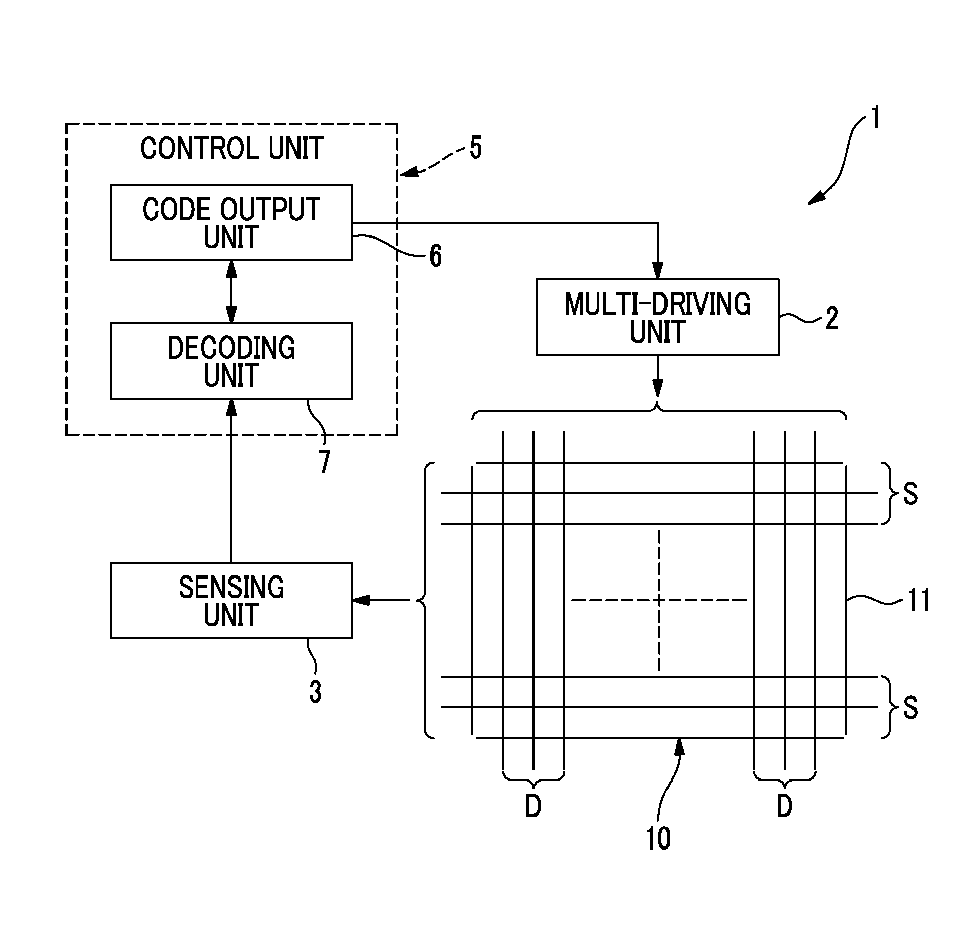
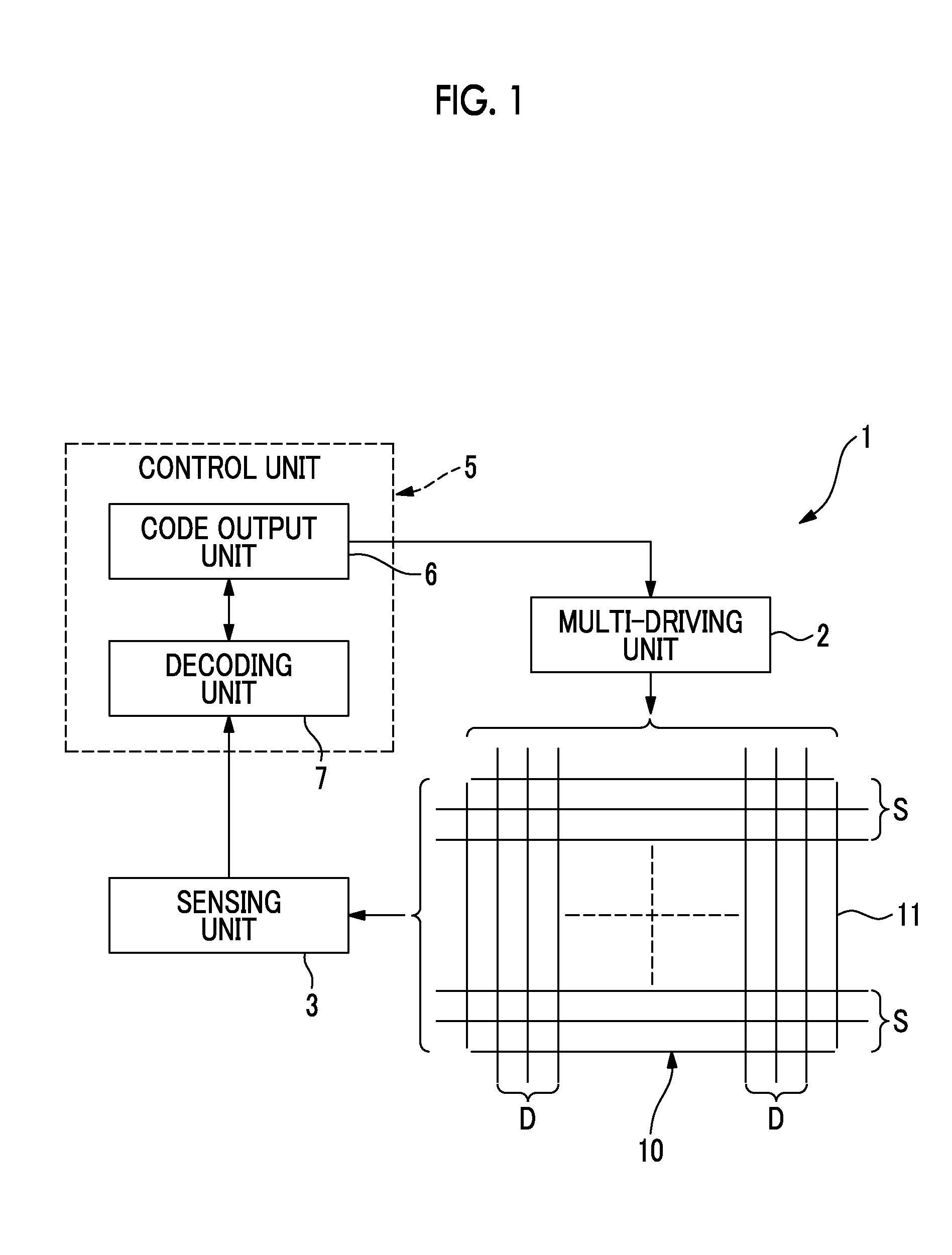
[0044]FIG. 1 is a block diagram illustrating a capacitive sensing device 1 of an embodiment of the present invention.

[0045]The capacitive sensing device 1 includes a touch pad 10. The touch pad 10 includes an insulating substrate 11. The insulating substrate 11 is a resin film, a resin substrate, or a glass substrate. When a display panel such as a liquid crystal panel is arranged on a back of the insulating substrate 11, the insulating substrate 11 is formed of a transparent material.

[0046]In the insulating substrate 11, a plurality of driving electrodes D formed in a column direction, and a plurality of sensing electrodes S formed in a row direction are provided. The driving electrode D and the sensing electrode S can be insulated from each other and formed to be orthogonal to each other.

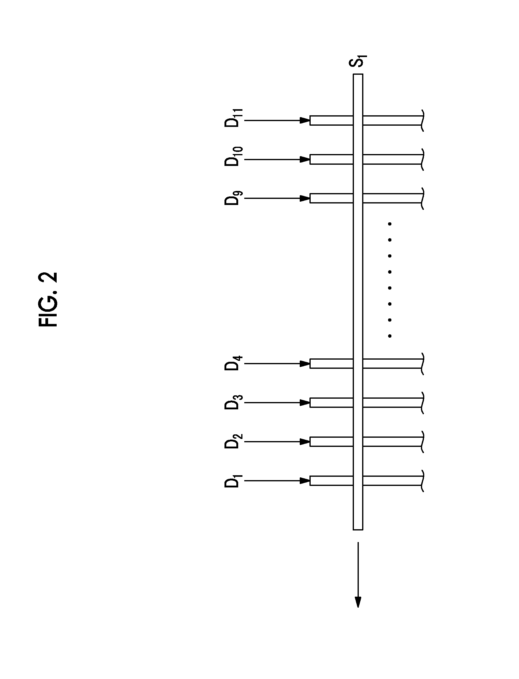
[0047]In FIGS. 1 and 2, the driving electrodes D and the sensing electrode S are in a stripe shape, and capacitance is mainly formed in an intersection po...


PUM


Abstract

A driving signal is applied to a plurality of driving electrodes using the driving matrix illustrated in FIG. 5A obtained by removing a row in which a sum of codes is greatest and a column having a transposition relationship with the row in a Hadamard matrix. Distribution of capacitance in intersection portions between a sensing electrode and a plurality of driving electrodes can be obtained using an inverse matrix of the driving matrix illustrated in FIG. 5B. Further, when decoding is performed using an extended matrix obtained by replacing “0” with “−1” in FIG. 5B, it is possible to average noise and to improve an S/N ratio.

Description

CLAIM OF PRIORITY[0001]This application claims benefit of Japanese Patent Application No. 2014-215705 filed on Oct. 22, 2014, which is hereby incorporated by reference.BACKGROUND OF THE INVENTION[0002]1. Field of the Invention[0003]The present invention relates to a capacitive sensing device in which capacitance is formed between a plurality of driving electrodes and at least one sensing electrode, and more particularly, to a capacitive sensing device of a multi-driving scheme in which a driving signal is simultaneously applied to a plurality of driving electrodes.[0004]2. Description of the Related Art[0005]A mutual capacitive sensing device and a self-capacitive capacitive sensing device are known as capacitive sensing devices including a touch pad. The mutual capacitive sensing device includes a plurality of driving electrodes formed in a column direction, and a plurality of sensing electrodes extending in a row direction. The driving electrode and the sensing electrode are insul...

Claims


Application Information

Patent Timeline
Patent Type & Authority Applications(United States)
IPC IPC(8): G06F3/041G09G3/20G06F3/044
CPCG06F3/0418G06F3/044G09G2300/0408G06F3/0412G09G3/20G06F3/04166G06F3/0446
Inventor SAGAWAI, SHINICHIMIYAKO, IKUYASU
Owner ALPS ALPINE CO LTD
Why Eureka
Try Eureka