Detecting CPD in HFC Network with OFDM Signals

a technology of detecting cpd and hfc network, which is applied in the direction of television system, transmission monitoring, two-way working system, etc., can solve the problems of increasing the difficulty of solving cpd impairment problems, task is a challenge, and common path distortion in modern hfc network

Active Publication Date: 2016-04-28
ARCOM DIGITAL
View PDF11 Cites 8 Cited by
  • Summary
  • Abstract
  • Description
  • Claims
  • Application Information

AI Technical Summary

Problems solved by technology

One type of impairment in a modern HFC network is common path distortion (CPD).
In addition, the locations of CPD sources are often locations where noise is introduced into the CATV network (i.e., ingress points).
However, this task is a challenge due to the hundreds and sometimes thousands of nodes, network components, and miles of network cable in a network.
In recently specified and implemented HFC networks (“modern HFC networks”), the CPD impairment problem is expected to become more difficult to solve due to several factors.
In the case of analog channels, CPD generally appears at harmonics of 6 MHz and is thus relatively easy to detect, while, in the case of QAM or other digital channels, CPD appears as flat noise spread over the full upstream spectrum, making it more difficult to detect.
But, in the case of an all-digital network (e.g., QAM and / or OFDM signals), CPD in the upstream spectrum looks like flat noise and is not easily distinguishable from additive ingress noise.
Another limitation is that a spectrum analyzer does not allow one to identify multiple sources of CPD, which is a typical impairment scenario.
Also, a CPD source cannot be directly located using a spectrum analyzer.
Further, a spectrum analyzer is unable to detect very low level CPD distortion products.
Thus, a common and full downstream spectrum of signals for use as a probe signal (as found in current or legacy networks) will not generally be available or possible in the recently specified networks.
Such devices may not accurately emulate high order IM products, expected with OFDM signals.
Further, for optimum CPD detection, a vacant part of the upstream spectrum should be used, because the relatively high level of upstream QAM data carriers (formed by cable modems) may interfere with typically low level CPD echo signals.
Generally, the vacant part of the upstream spectrum is 5 to 20 MHz, but this part of the spectrum is noisy due to ingress.
Ingress can limit the sensitivity of the CPD radar.
If the bandwidth of the CPD radar is limited to minimize ingress, the limited bandwidth will limit the sensitivity and time delay resolution of the CPD radar.
Such extra equipment would require extra space and power consumption.
(www.aurora.com), where the CMTS card is installed directly at the fiber node, convenient connection to upstream test points to receive CPD echo signals may be impossible.
However, in reality, it is not so simple.
For instance, such a predictive method does not yield an actual CPD level in the upstream spectrum, because the relative CPD level in the upstream depends on the upstream signal level at the CPD source.
Further, the level of third order IM products in the downstream cannot be used as a reliable indicator of CPD, because third order IM is generated at all amplifiers and only those amplifiers with, e.g., a poor performing diplex filter will produce CPD.
Thus, in general, one cannot distinguish, among all amplifiers, which one is the CPD source.
Lastly, the above predictive method does not directly identify a correct number and location of the CPD sources in the node.
That is, the method does not distinguish between nonlinear distortions from, e.g., CPD and amplifiers operating in a nonlinear region.
This is true in the sense that a nonlinear element, such as a corroded center conductor, may also create an impedance mismatch, which may generate a micro-reflection (a linear distortion).
But, relying on whether a nonlinear element also has a linear distortion associated with it, is an indirect and imperfect assessment.

Method used


Image

  • Detecting CPD in HFC Network with OFDM Signals
  • Detecting CPD in HFC Network with OFDM Signals
  • Detecting CPD in HFC Network with OFDM Signals

Examples


first embodiment

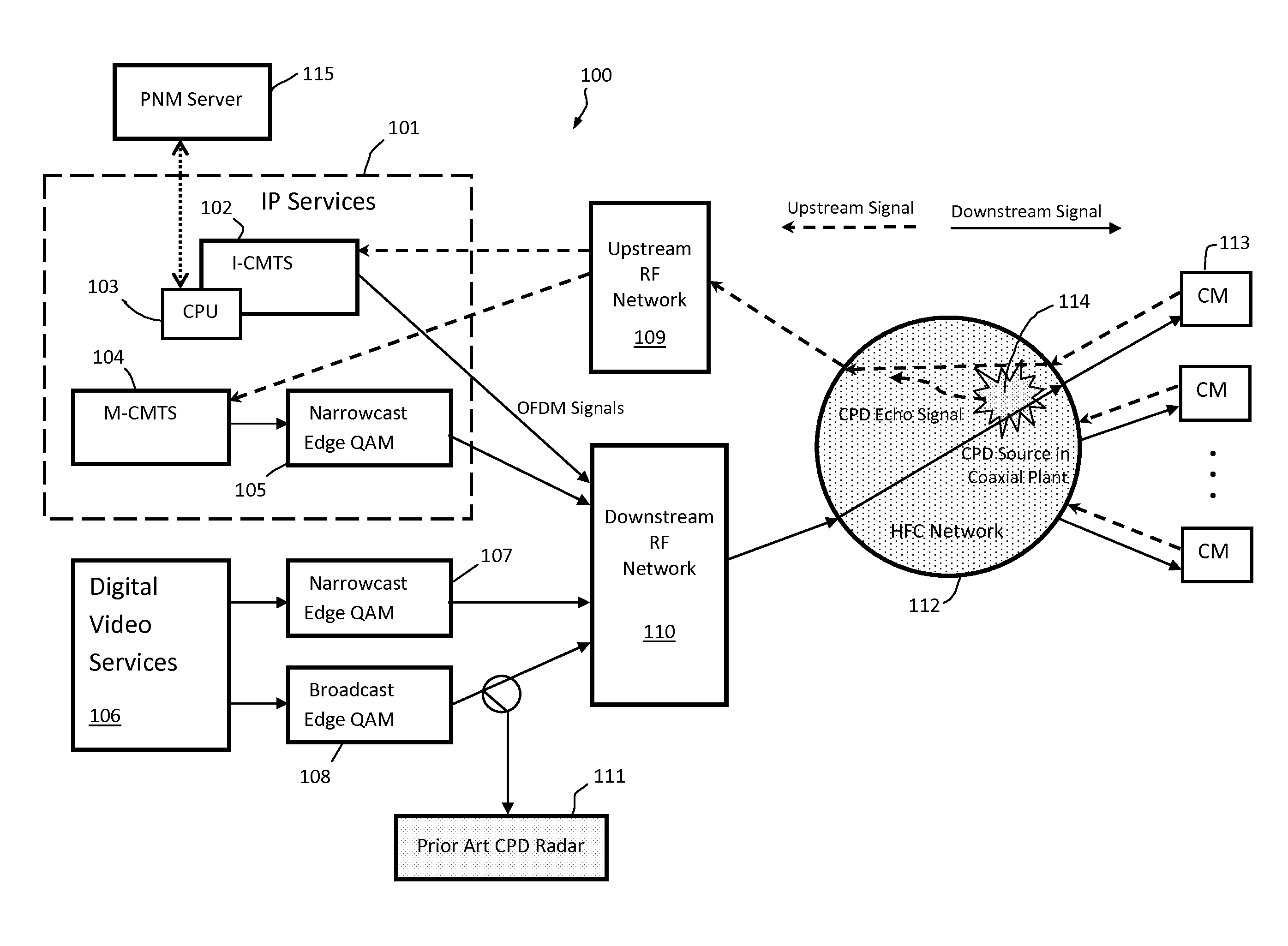
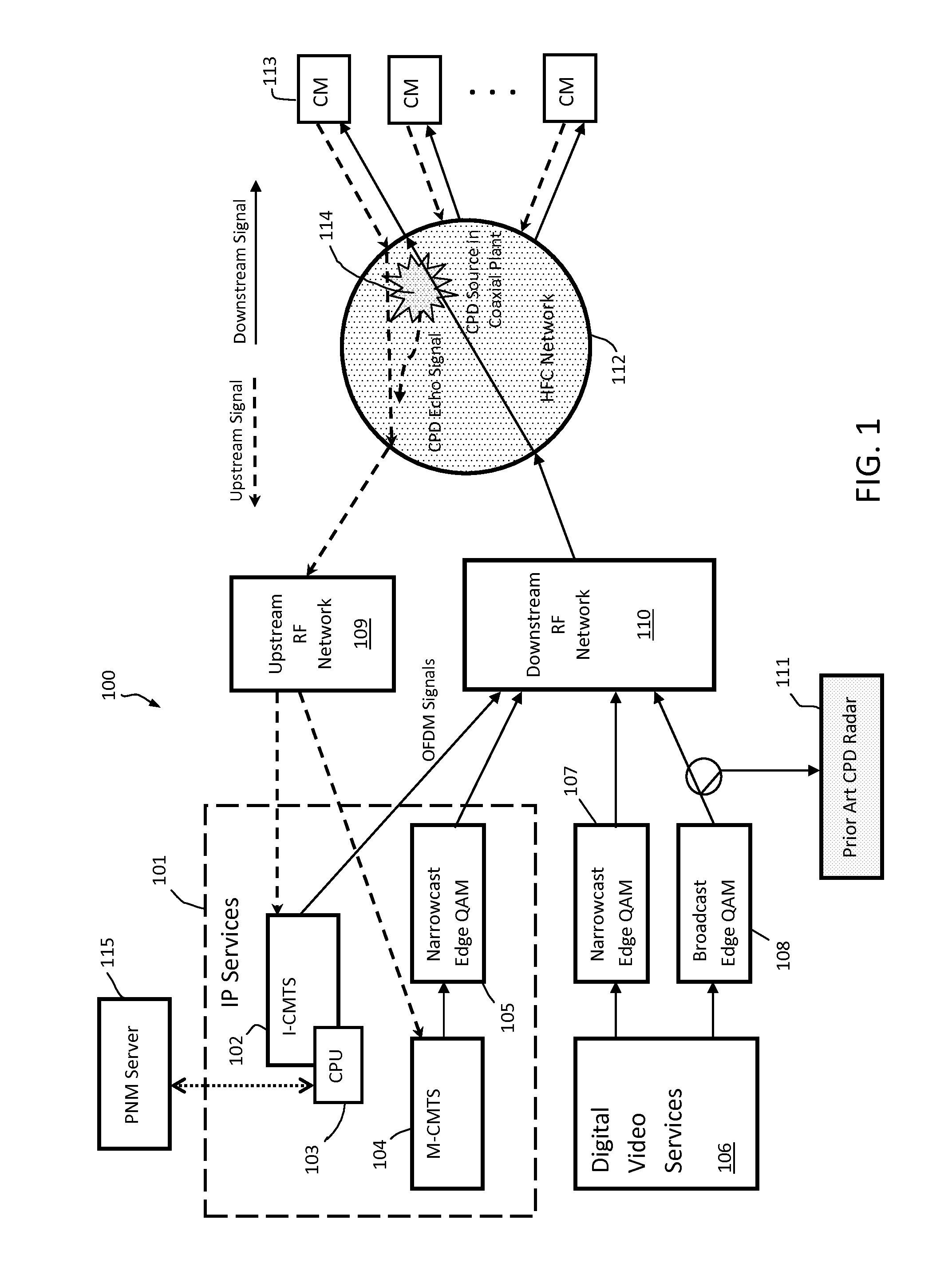
[0054]Now returning to FIG. 5 and time diagrams 511 and 514, the discussion of the first embodiment continues. After moment 510 (downstream transmission of RF version of symbol 501), the CMTS (e.g., I-CMTS 102) and server 115 begin to capture or otherwise acquire (the samples of) an upstream OFDM symbol 505 at a moment 516. The time delay between moments 510 and 516 is set by the CMTS scheduler according to two criteria: (1) upstream symbol 505 should be a quiet probe symbol (see DOCSIS 3.1, Section 9.4.1); and (2) the time delay should be equal to the expected round-trip time of an RF signal transmitted from the CMTS to the fiber node, plus or minus a few microseconds. The first criterion is intended to ensure that symbol 505 is captured when the CMs are not transmitting, so there are no signals interfering with the receipt of a CPD echo signal. The second criterion is intended to ensure that the CPD echo signal (formed by downstream symbol 501 at a CPD source) is captured or other...

second embodiment

[0060]Turning now to second embodiment, the method of which is understood by the flow diagram of FIG. 7 and time diagrams 511 and 515 in FIG. 5. The method of the second embodiment is essentially the same as the method of first embodiment, except that the CMTS captures full-band upstream time-domain samples during a quiet period (instead of an upstream quiet symbol in the OFDM upstream channel). The method steps 701-705 and 708-713 in FIG. 7 are essentially the same as steps 601-605 and 608-613 in FIG. 6, respectively. Also, signals 714-718 in FIG. 7 are the same as signals 614-618 in FIG. 6, respectively. Therefore, the steps in the second embodiment that relate only to the capture of the full-band upstream time-domain samples by the CMTS (and by server 115 via the CMTS) will be described in detail.

[0061]According DOCSIS 3.1 specifications, section 9.4.2, “The CMTS should be capable of providing the time-domain input samples as an alternative to the frequency-domain upstream spectr...

third embodiment

[0064]Turning now to the third embodiment, the method of which is understood by the flow diagram of FIG. 8 and time diagrams 511-513 and 515 in FIG. 5. In a first step 801 (FIG. 8), full-band downstream time-domain samples are captured by a CMTS (e.g., I-CMTS 102) beginning at moment in time 510 (FIG. 5) or by a CM (e.g., CMs 113) at a moment in time 518 (FIG. 5). These samples are retrieved from the CMTS or CM(s) by server 115 for further processing in accordance with the method. As indicated before, the capture of full-band downstream time-domain samples by the CMTS is not a mode required by current DOCSIS specifications. But, technically, it is not a problem to implement such a mode in the CMTS.

[0065]The capture of full-band downstream time-domain samples at a CM is required by DOCSIS 3.1 specifications, but the triggering mode for capturing the samples is not defined. The DOCSIS 3.1 specification states the following with respect to a trigger: “The CM must be capable of locating...


PUM


Abstract

A apparatus or method for detecting CPD in an HFC network, comprising: (a) acquiring digital RF downstream signals from a CMTS or CM; (b) emulating even and odd order IM distortion products from the downstream signals; (c) acquiring RF upstream signals from the CMTS during a quiet period; (d) cross-correlating the RF upstream signals with the emulated even and odd order IM products to produce even and odd order cross-correlation functions, respectively; (e) accumulating, separately, a multiplicity of even and odd order cross-correlation functions; (f) calculating even and odd order cross-correlation envelopes from the accumulated even and odd order cross-correlation functions, respectively; and (g) detecting a CPD source from either or both of the even and odd order cross-correlation envelopes by the presence of a peak in either or both of the envelopes.

Description

CROSS-REFERENCE TO RELATED APPLICATIONS[0001]This application claims the benefit of U.S. Provisional Application No. 62 / 067,002, filed Oct. 22, 2014.BACKGROUND OF THE INVENTION[0002]1. Field of Invention[0003]The present invention relates generally to monitoring impairments in a CATV or HFC network, and more particularly methods and apparatus for pinpointing nonlinear impairments such as common path distortion (CPD) and passive intermodulation distortion (PIM) in a modern CATV or HFC network transmitting OFDM signals.[0004]2. Background Art[0005]One type of impairment in a modern HFC network is common path distortion (CPD). This impairment is nonlinear and involves the intermodulation of forward path (or down stream) signals occurring at various network components in the “common path” (i.e., both forward and return paths) of the network, such as amplifiers, connectors, taps, terminations, etc. The intermodulation of the forward path signals is the result of a so-called “diode effect...

Claims


Application Information

Patent Timeline
Patent Type & Authority Applications(United States)
IPC IPC(8): H04N21/24H04N21/2385H04N21/242H04L27/26
CPCH04N21/2404H04N21/242H04N21/2385H04L27/2601H04B17/0085H04L1/206
Inventor ZINEVICH, VICTOR M.
Owner ARCOM DIGITAL
Why Eureka
Try Eureka