Shelving structure

a technology of shelving structure and shelving plate, which is applied in the direction of display hangers, dismountable cabinets, cabinets, etc., can solve the problems of high defect rate and higher manufacture cost, and achieve the effect of easy manufacturing and better stability

Inactive Publication Date: 2016-05-05
PROMAL
View PDF1 Cites 10 Cited by
  • Summary
  • Abstract
  • Description
  • Claims
  • Application Information

AI Technical Summary

Benefits of technology

[0006]An objective of the present invention is to provide a shelving structure which is easy to manufacture and providing better steadiness.
[0008]In one objective of the present invention, the width of the second securing lip is ⅓ or ¼ of the width of the first securing lip, therefore, the woven body can be easily placed into the frame member from the second securing lip. Furthermore, the edge of the woven body contacts the side of the first securing lip facing the second securing lip and also is welded onto the woven body to be secured onto the first securing lip. Since the second securing lip is narrower than the first securing lip, it is easy to perform the welding procedure.
[0009]Furthermore, in another objective of the present invention, the frame member is provided with the plurality of supporting rod below the woven body correspondingly perpendicular to the second securing lip of the supporting loop, to enhance the strength of the frame member and improve the pressurization strength of the woven body. Therefore, the frame member and the woven body require less material, and an efficient welding area between the first securing lip and the woven body provides strong support around the woven body.

Problems solved by technology

However, the above-mentioned typical shelving structure has following problems: The complex assembly process causes higher defect rate and higher manufacture cost.

Method used


Image

  • Shelving structure
  • Shelving structure
  • Shelving structure

Examples


Embodiment Construction

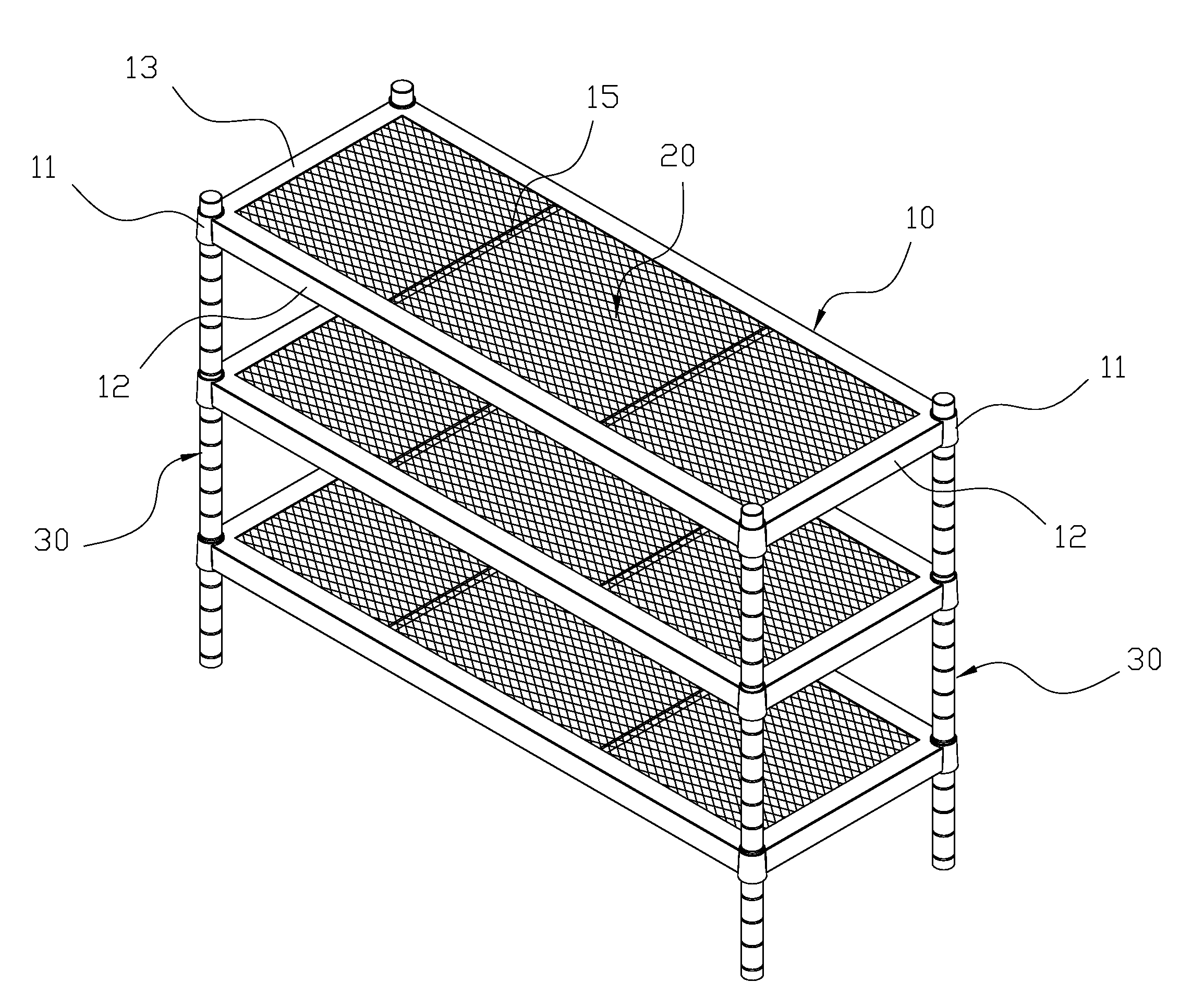
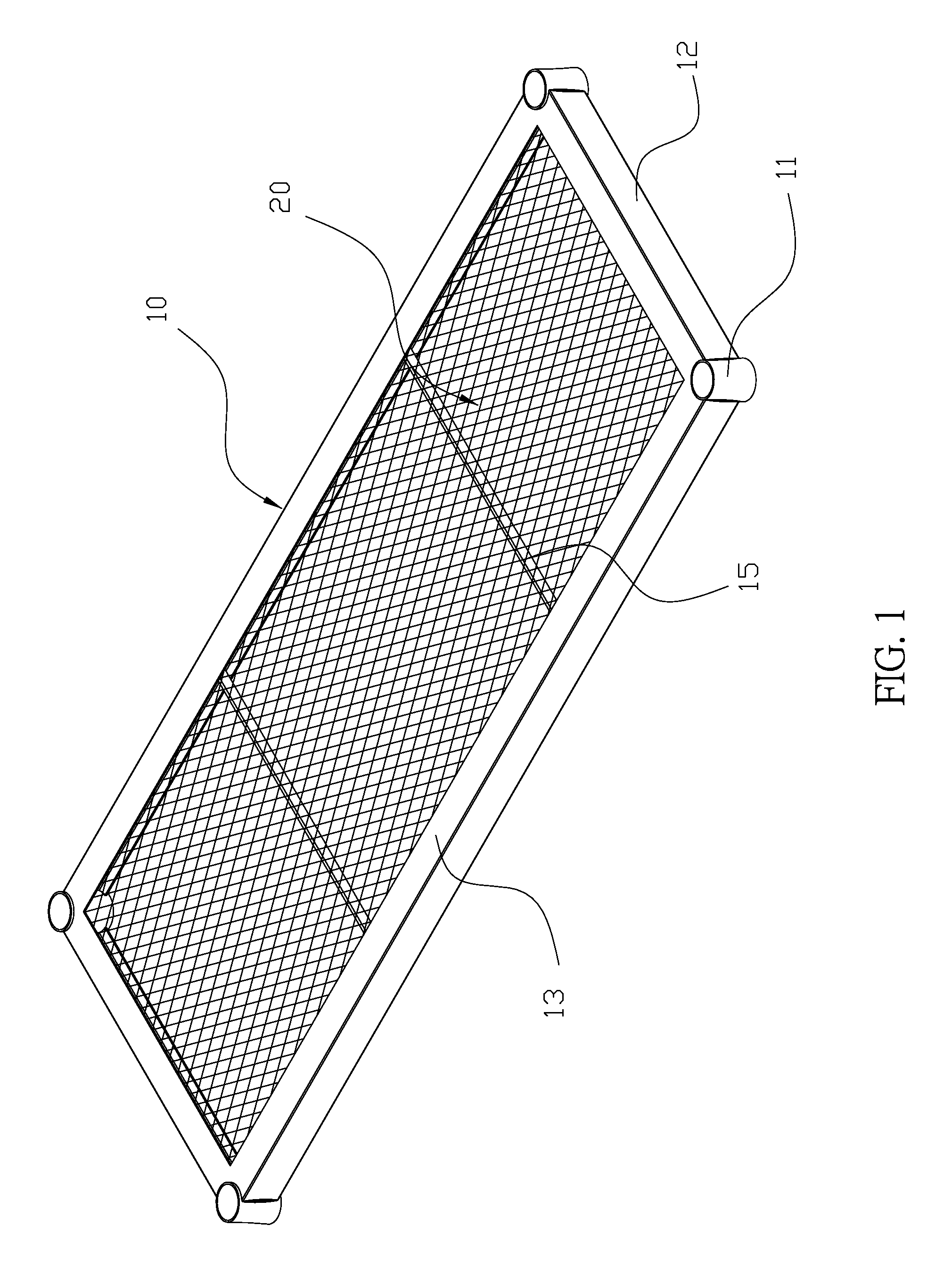
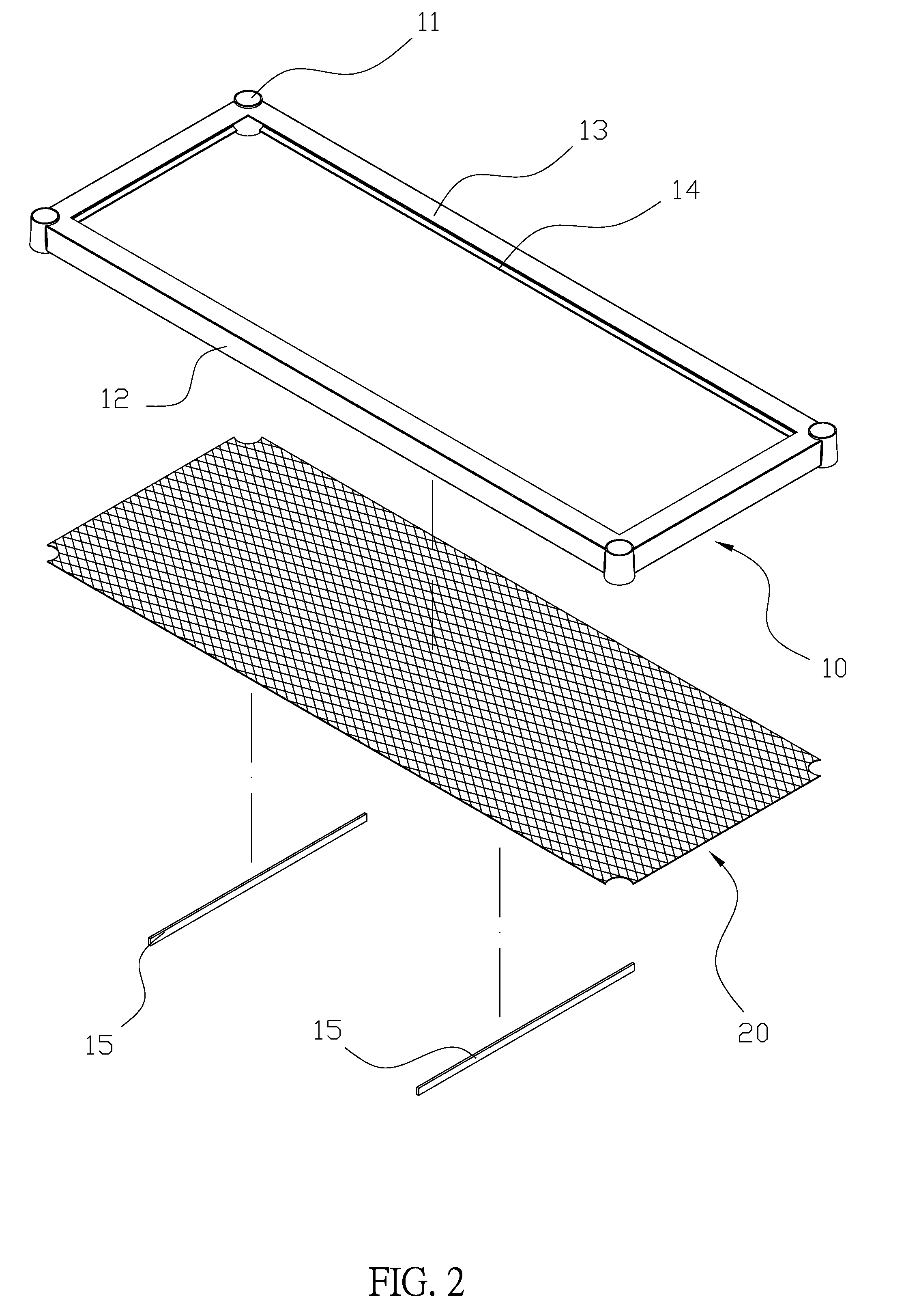
[0016]Please refer to FIGS. 1, 2 and 3. A shelving structure comprises a frame member 10 and a woven body 20. The frame member 10 has a rectangular shape and a respective connecting pipe 11 disposed at four corners thereof, and each connecting pipe 11 is connected to a supporting loop 12. An upper edge of the supporting loop 12 is provided with a first securing lip 13 and a lower edge of the supporting loop 12 is provided with a second securing lip 14 parallel to the first securing lip 13. A width of the second securing lip 14 is smaller than a width of the first securing lip 13, and preferably the width of the second securing lip 14 is ¼ to ⅓ of the width of the first securing lip 13. The woven body 20 has a shape corresponding to an enclosed space formed by the connecting pipes 11 and the supporting loop 12, and the woven body 20 extends from the second securing lip 14 into the frame member 10 and is welded onto the first securing lip 13 facing the second securing lip 14. The fram...


PUM

PropertyMeasurementUnit
shelving structureaaaaaaaaaa
widthaaaaaaaaaa
shapeaaaaaaaaaa

Abstract

A shelving structure has a frame member and a woven body. The frame member has a rectangular shape and a respective connecting pipe disposed at four corners thereof, and each connecting pipe is connected to a supporting loop. An upper edge of the supporting loop is provided with a first securing lip and a lower edge of the supporting loop is provided with a second securing lip parallel to the first securing lip. A width of the second securing lip is smaller than a width of the first securing lip. The woven body has a shape corresponding to an enclosed space formed by the connecting pipes and the supporting loop, and the woven body extends from the second securing lip into the frame member and is welded onto the first securing lip. The frame member is provided with a plurality of supporting below the woven body.

Description

BACKGROUND OF THE INVENTION[0001]1. Field of the Invention[0002]The present invention relates to a shelving structure, and more particularly to a shelving structure having strong strength and low manufacturing cost.[0003]2. Description of the Related Art[0004]Currently, a typical shelving structure, as shown in FIGS. 5 and 6, includes a frame member 40 and a woven body 50, each of four ends of the frame member 40 is provided with a sleeve tube 41 which is individually welded onto four supporting loops 42. Furthermore, both an upper edge and an lower edge of the supporting loop 42 are individually provided with a extending lip 43 parallel with each other, and the woven body 50 is welded on to an inner side of the extending lip 43 of the upper edge of the supporting loop 42. For assembly, two adjacent supporting loops 42 need to be welded onto the sleeve tube 41 and the woven body 50 is placed between the two extending lips 43 of the two supporting loops 42, the other two supporting l...

Claims


Application Information

Patent Timeline
Patent Type & Authority Applications(United States)
IPC IPC(8): A47B96/02A47B47/00
CPCA47B96/021A47B47/0091A47B47/0083A47B47/00A47B57/06A47F5/00
Inventor TANG, PAO-HSUN
Owner PROMAL
Why Eureka
Try Eureka