
Disposable endoscope sheath

Inactive Publication Date: 2016-05-05
TIANJIN BOLANG SCI TECH DEV
View PDF22 Cites 19 Cited by
  • Summary
  • Abstract
  • Description
  • Claims
  • Application Information

AI Technical Summary

Benefits of technology

The present invention provides an endoscope sheath with a metal tube for better maneuverability in surgery, adjustable instrument angle, and avoidance of cross infection. It can be used with different lengths of endoscopes and has a disposable locking mechanism to prevent reuse. It also has scale marks to indicate insertion depth and a protective cover to prevent contamination. These features make it easy to use and marketable.

Problems solved by technology

Humoral substances generated during the surgery on the human body pollute the endoscope, and the endoscope must be sterilized after the surgery.
However, such scope sheath structure also has the problems.
If the sheath length is not adjustable, when the endoscope is too long, it may penetrate out of the protective structure of the sheath head of the endoscope sheath, causing injury to the human body; when the endoscope is too short, the rear end of the endoscope sheath cannot shrink and lock the endoscope, affecting the use of the endoscope.
Besides, the locking structure in this solution can be repeatedly used after the endoscope is dismantled at the end of the surgery, tending to cause cross infection.
Due to the limited cross section area of the sheath tube of the endoscope sheath, how to rationally locate the above-mentioned channel to meet the different demands of the modern surgeries is also a technical problem in this field.
On the other hand, in the endoscopic surgery, sometimes it is difficult for the medical personnel to judge the insertion depth of the sheath tube of the endoscope sheath, so a means for clearly representing the insertion depth of the sheath tube is also needed.
In the current surgeries, sometimes a lot of body fluids may occur because of excessive bleeding of the patient, etc.

Method used


Image

  • Disposable endoscope sheath
  • Disposable endoscope sheath
  • Disposable endoscope sheath

Examples


Embodiment Construction

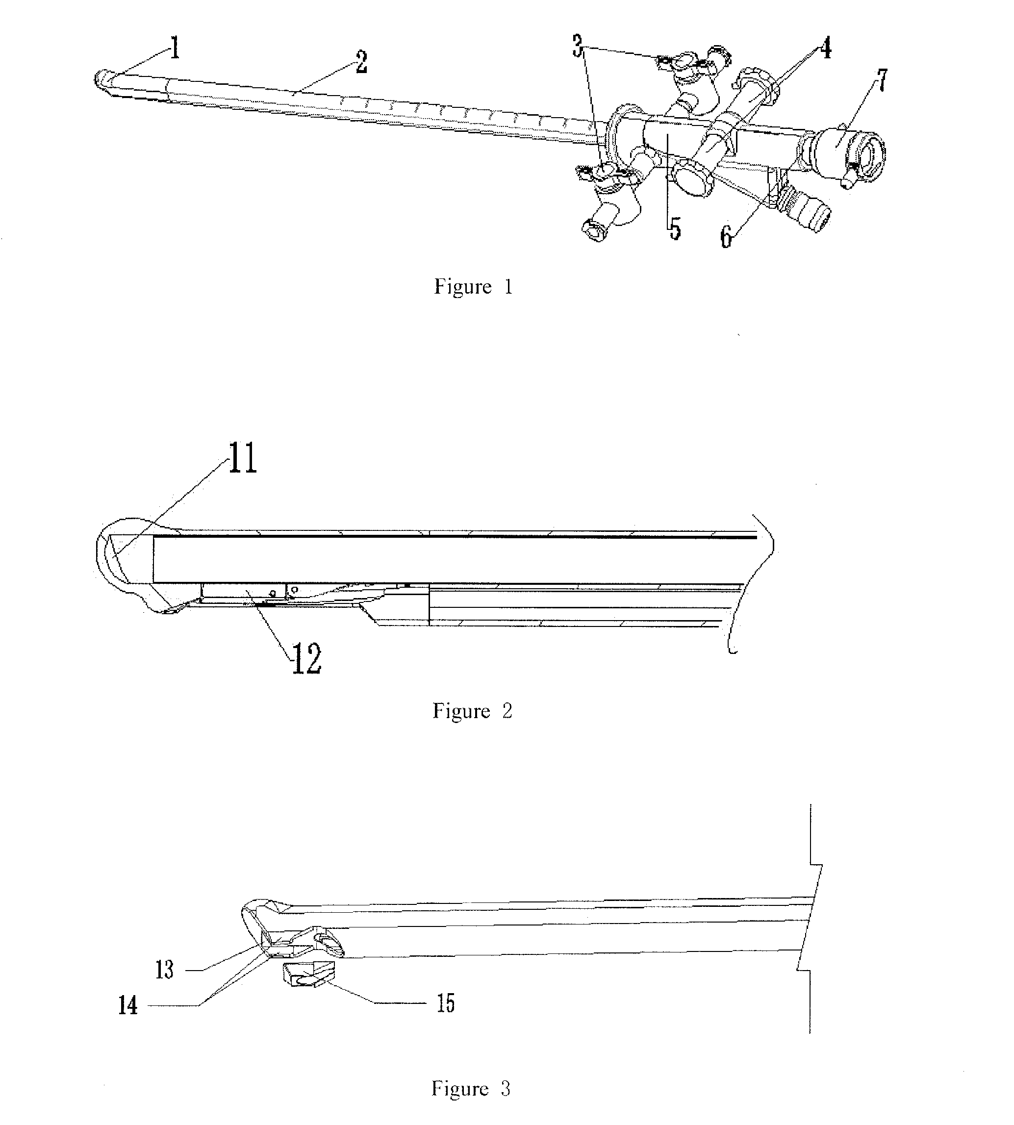
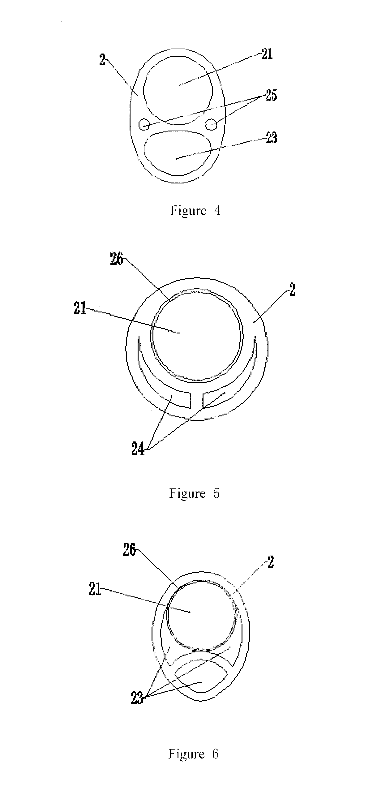
[0036]As shown in FIGS. 1-14, the disposable endoscope sheath comprises an insertion portion, a control portion, an endoscope locking portion; wherein, the insertion portion comprises a sheath head 1 and a sheath tube 2; the control portion comprises a main body 5, a water inlet and outlet valve 3 and an instrument adjusting knob 4; the endoscope locking portion comprises an extension endoscope bridge 6 and a locking sleeve 7; the sheath head is located at the front end of the insertion portion and is connected with the sheath tube in the rear; the sheath tube is connected with the extension endoscope bridge through the main body; the water inlet and outlet valve and the instrument adjusting knob are located on the main body of the endoscope sheath; the lower part of the front end of the sheath tube is provided with a lifting device 12; the sheath head is provided with an arc-shaped transparent widow 11; the sheath tube comprises an endoscope cavity 21, an instrument channel 22, a w...


PUM


Abstract

The present invention discloses a disposable endoscope sheath, comprising an insertion portion, a control portion and an endoscope locking portion, wherein the insertion portion comprises a sheath head and a sheath tube; the control portion comprises a main body, a water inlet and outlet valve and an instrument adjusting knob; and the endoscope locking portion comprises an extension endoscope bridge, a locking sleeve and a protective cover. The sheath head is located at the front end of the insertion portion and is connected with the sheath tube in the rear. The sheath tube is connected with the extension endoscope bridge of the endoscope locking portion through a main body. The water inlet and outlet valve and the instrument adjusting knob are located on the main body of the endoscope sheath. The sheath tube is a multi-channel structure, and the outer surface of the insertion portion has scale marks. The present invention has the beneficial effects in that the disposal use avoids cross infection, and the demands of different endoscopic surgeries can be satisfied.

Description

BACKGROUND OF THE INVENTION[0001]1. Technical Field[0002]The present invention belongs to the technical field of medical instruments, in particular, to a disposable endoscope sheath.[0003]2. Description of Related Art[0004]Conventional cystoscope instruments and hysteroscope instruments are mainly made of stainless steel, while the stainless steel surgical instruments belong to open instruments and cannot completely close an endoscope in use. During surgery, the endoscope works while being inserting into instruments like a sheath. Humoral substances generated during the surgery on the human body pollute the endoscope, and the endoscope must be sterilized after the surgery. Currently, a kind of endoscope sheath which performs fully-closed protection is available on the market. The endoscope is inside, while the sheath is outside. The endoscope does not contact with anyone, so it is the endoscope sheath that contacts the human body. The human body does not pollute the endoscope, thus ...

Claims


Application Information

Patent Timeline
IPC IPC(8): A61B1/00A61B1/018A61B1/04A61B1/015
CPCA61B1/00135A61B1/00103A61B1/015A61B1/018A61B1/04A61B1/00066A61B1/00073A61B1/00114A61B1/0014A61B2017/0034A61B1/00098A61B1/00142
Inventor QI, LIN
Owner TIANJIN BOLANG SCI TECH DEV
Learn More