
Leadless dual-chamber pacing system and method

a dual-chamber, leadless technology, applied in power management, synchronisation arrangement, therapy, etc., can solve the problems of requiring multiple leads, unable to communicate with the patient, and pacemakers with left ventricle pacing/sensing capability require multiple leads,

Active Publication Date: 2016-05-05
PACESETTER INC
View PDF1 Cites 145 Cited by
  • Summary
  • Abstract
  • Description
  • Claims
  • Application Information

AI Technical Summary

Benefits of technology

This patent describes a system for communicating between two implantable medical devices (IMDs) that can apply cardiac stimulation to a patient. The first IMD sends an event message to the second IMD, which responds by generating pacing pulses for a predetermined number of consecutive cardiac cycles. The second IMD also initiates a timer to deliver the pacing pulse at a specific time. This system can be used to provide more efficient and targeted cardiac stimulation therapy for patients with heart disease.

Problems solved by technology

These leads may experience certain limitations, such as incidences of venous stenosis or thrombosis, device-related endocarditis, lead perforation of the tricuspid valve and concomitant tricuspid stenosis; and lacerations of the right atrium, superior vena cava, and innominate vein or pulmonary embolization of electrode fragments during lead extraction.
Further, conventional pacemakers with left ventricle (LV) pacing / sensing capability require multiple leads and a complex header on the pacemaker.
The LPs that have been proposed thus far offer limited functional capability.
For example, an LP device that is located in the right atrium would be limited to offering AAI mode functionality.
Similarly, an LP device that is located in the right ventricle would be limited to offering VVI mode functionality.
These AP commands could in theory have a risk of inducing premature ventricular excitations, which under worst-case consideration, could degenerate into sustained ventricular tachycardia or ventricular fibrillation, which may be lethal to the patient.

Method used


Image

  • Leadless dual-chamber pacing system and method
  • Leadless dual-chamber pacing system and method
  • Leadless dual-chamber pacing system and method

Examples


Embodiment Construction

[0033]In some embodiments of an illustrative cardiac pacing system, pacing and sensing operations of multiple medical devices, which may include one or more leadless cardiac pacemakers, an ICD, such as a subcutaneous-ICD, and / or a programmer reliably and safely coordinate pacing and / or sensing operations.

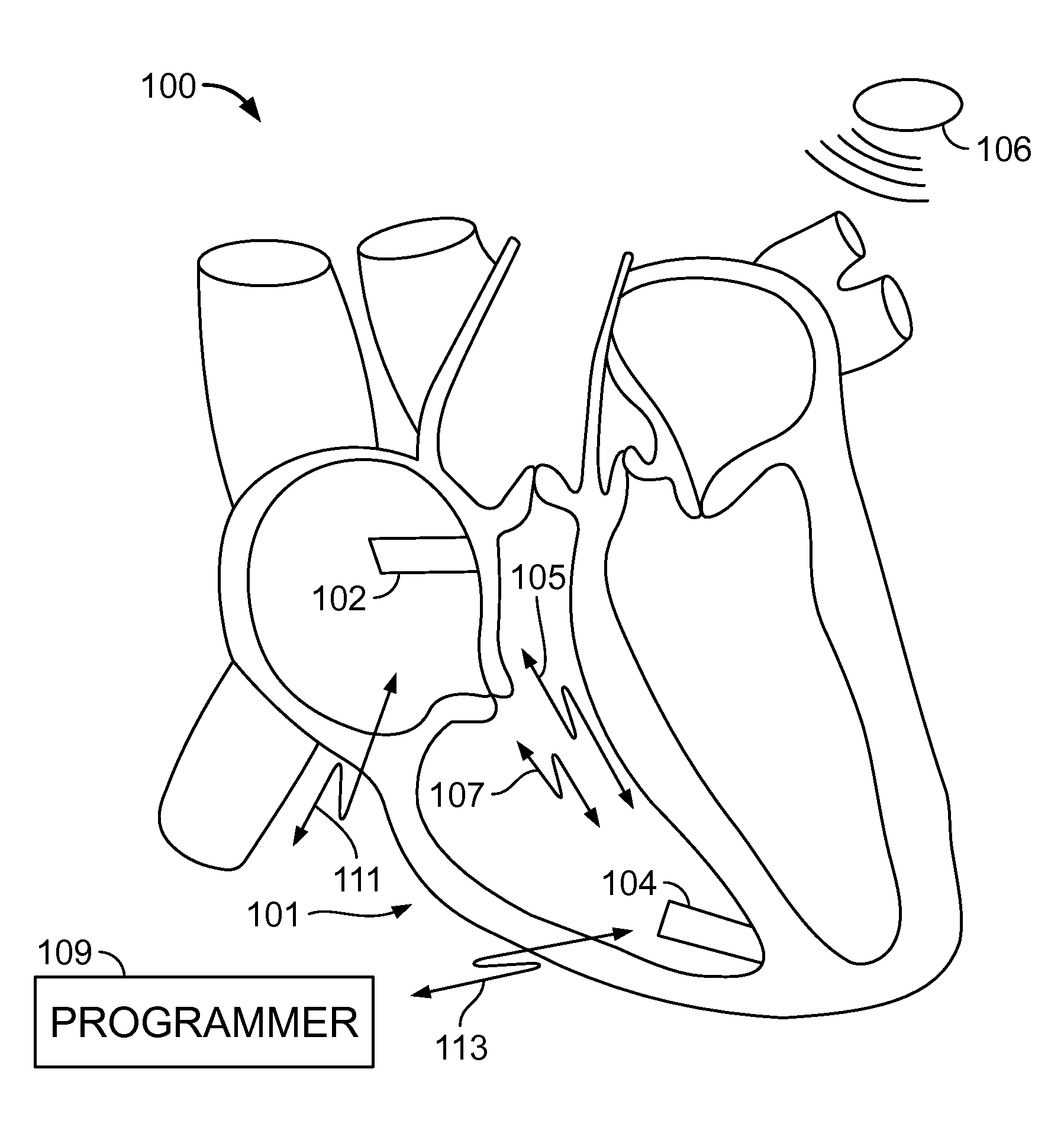
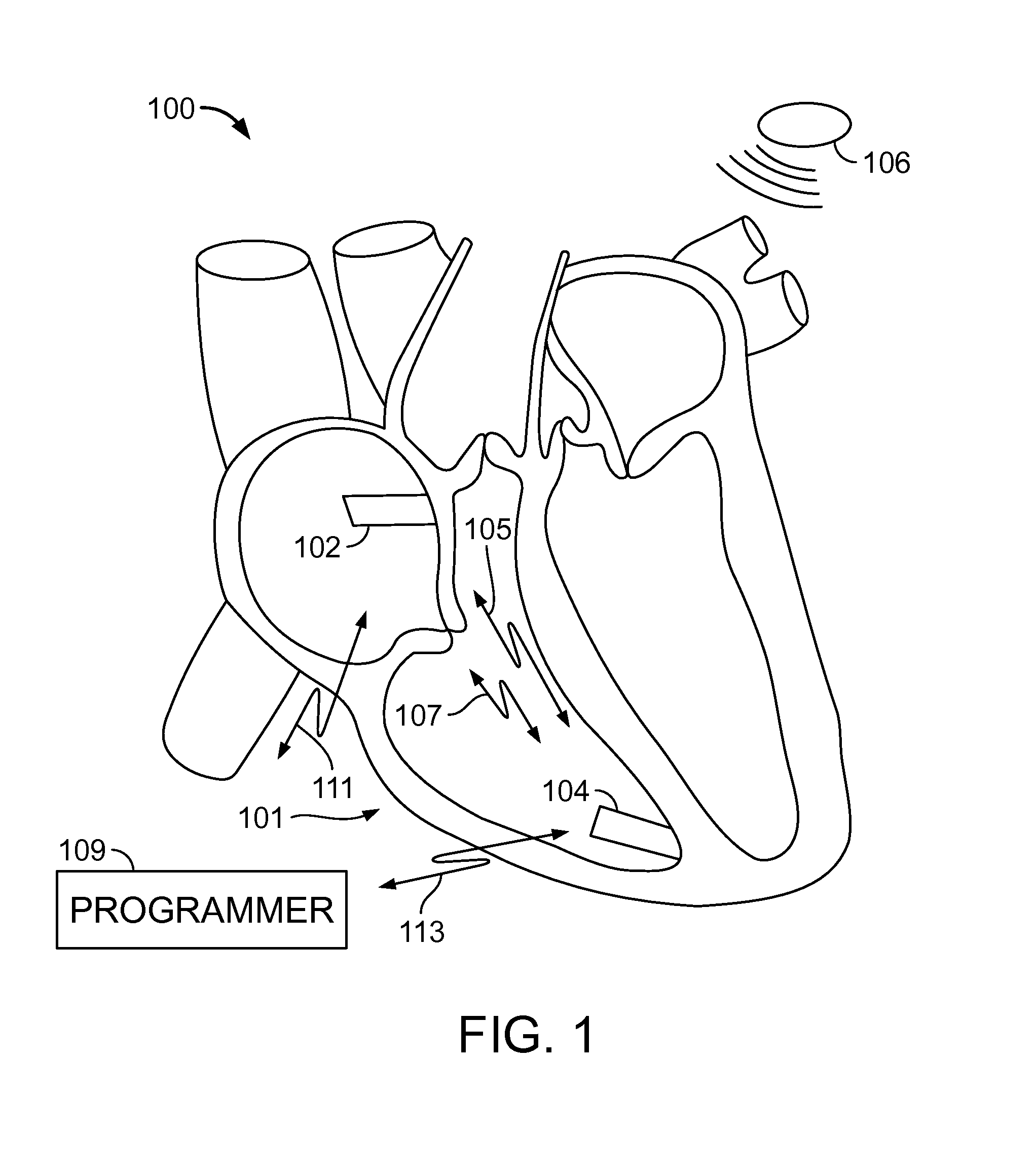
[0034]FIG. 1 illustrates a system 100 formed in accordance with embodiments herein as implanted in a heart 101. The system 100 comprises two or more leadless pacemakers (LPs) 102 and 104 located in different chambers of the heart. LP 102 is located in a right atrium, while LP 104 is located in a right ventricle. LPs 102 and 104 communicate with one another to inform one another of various local physiologic activities, such as local intrinsic events, local paced events and the like. LPs 102 and 104 may be constructed in a similar manner, but operate differently based upon which chamber LP 102 or 104 is located.

[0035]In some embodiments, LPs 102 and 104 communicate with one another, w...


PUM


Abstract

In accordance with an embodiment, a system and method is provided for providing communications between first and second implantable medical devices (IMDs). The system comprises a first implantable medical device (IMD) configured to transmit a first event message during or preceding a first cardiac cycle, and a second IMD configured to receive the first event message, wherein receipt of the first event message configures the second IMD to generate pacing pulses for only a predetermined number (“n”) of consecutive cardiac cycles, wherein n is an integer equal to or greater than 2. The method comprises transmitting a first event message during or preceding a first cardiac cycle from the first IMD, receiving the first event message at the second IMD, in response to receiving the first event message, arming the second IMD to generate a pacing pulse for a second cardiac cycle, and arming the second IMD to generate a pacing pulse for only a predetermined number of consecutive cardiac cycles immediately subsequent to the second cardiac cycle.

Description

CROSS REFERENCE TO RELATED APPLICATIONS[0001]This application claims the benefit of U.S. Provisional Application No. 62 / 084,476, entitled IMPLANTABLE DEVICE INTRA-CARDIAC COMMUNICATIONS SYSTEM AND METHOD, filed Nov. 25, 2014. This application also claims the benefit of U.S. Provisional Application No. 62 / 074,541, entitled IMPLANTABLE DEVICE INTRA-CARDIAC COMMUNICATIONS SYSTEM AND METHOD, filed Nov. 3, 2014. Each patent application identified above is incorporated herein by reference in its entirety to provide continuity of disclosure.FIELD OF THE INVENTION[0002]Embodiments herein generally relate to methods and systems for communication between implantable devices.BACKGROUND OF THE INVENTION[0003]Currently, implantable medical devices (IMDs) utilize one or more electrically-conductive leads (which traverse blood vessels and heart chambers) in order to connect a canister with electronics and a power source (the can) to electrodes affixed to the heart for the purpose of electrically e...

Claims


Application Information

Patent Timeline
Patent Type & Authority Applications(United States)
IPC IPC(8): A61N1/372A61N1/365A61N1/375A61N1/362
CPCA61N1/37288A61N1/3756A61N1/36514A61N1/3622A61N1/3702A61N1/37217A61N1/37235H04W52/04H04W56/001
Inventor FISHLER, MATTHEW G.PERSSON, BENJAMIN T.GURUNATHAN, SURESHCHIN, DONALDSWIFT, STEPHEN J.
Owner PACESETTER INC
Learn More