Automatic canvas wrapping machine

Active Publication Date: 2016-05-05
SANLUX
View PDF0 Cites 0 Cited by
  • Summary
  • Abstract
  • Description
  • Claims
  • Application Information

AI Technical Summary

Benefits of technology

The present invention is about a machine that automatically wraps canvas around a yarn core. The machine has a device that drives the yarn core to rotate and attach it to the rubberized canvas. During this process, a device moves back and forth to press the canvas tightly around the yarn core. The machine also has a cutting device that automatically cuts off the canvas when the wrapping is complete. This invention improves the precision of the wrapping and increases the yield of products.

Problems solved by technology

This wrapping apparatus has the defect that the precision of manually cutting the base compound rubber and the rubberized canvas is poor.
When the base compound rubber is drawn and attached, the base compound rubber may not be uniformly drawn according to technical requirements, so that the weight uniformity of the base compound rubber is affected, defective thin belts are easily produced, the canvas wrapping precision is low, and the defective rate is high.
Moreover, according to the existing rubberized canvas wrapping apparatus for the rubber V-belt, a person only operates one wrapping apparatus, so that the production efficiency is low and the corresponding manufacture cost is high.

Method used


Image

  • Automatic canvas wrapping machine
  • Automatic canvas wrapping machine
  • Automatic canvas wrapping machine

Examples


Embodiment Construction

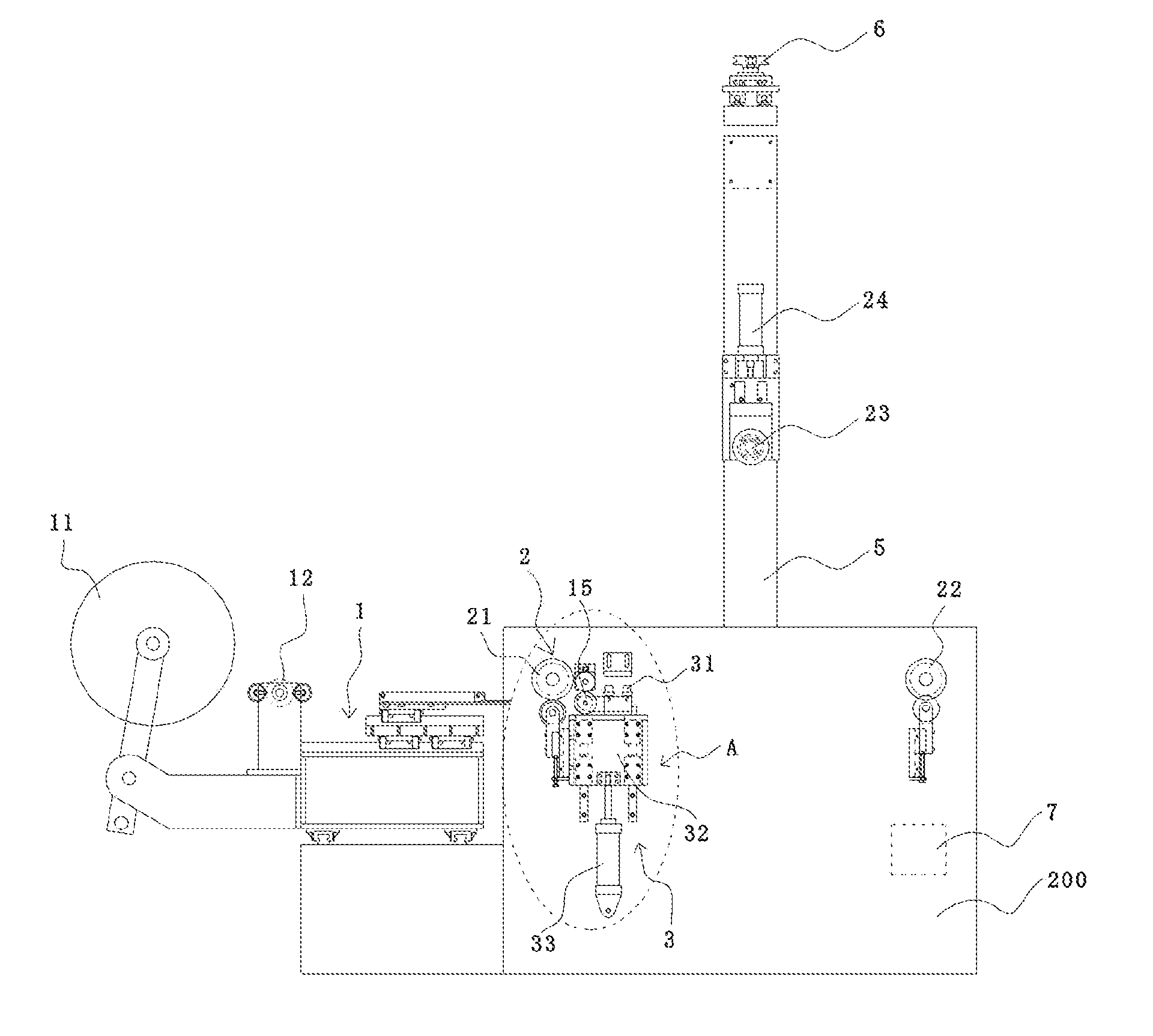
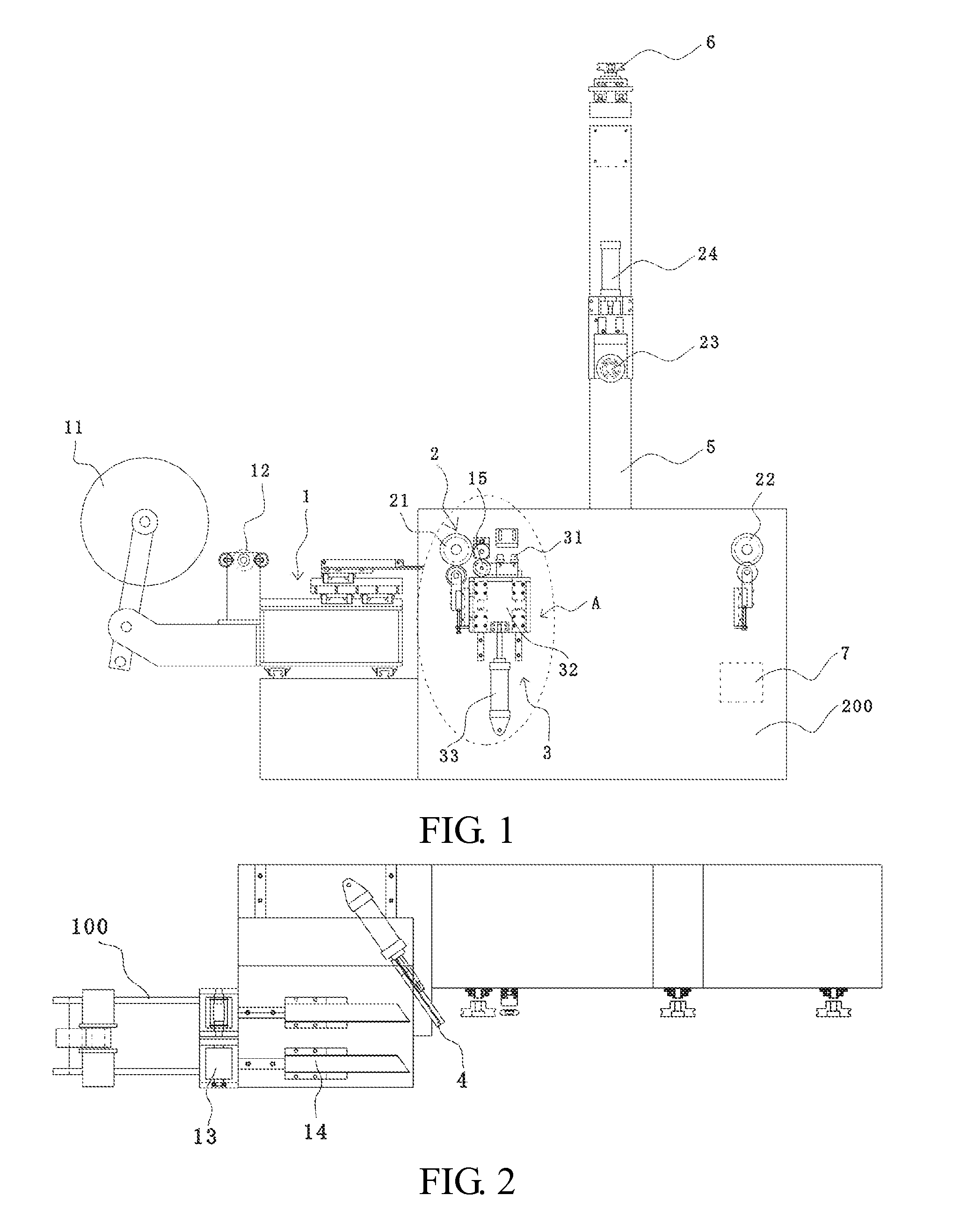
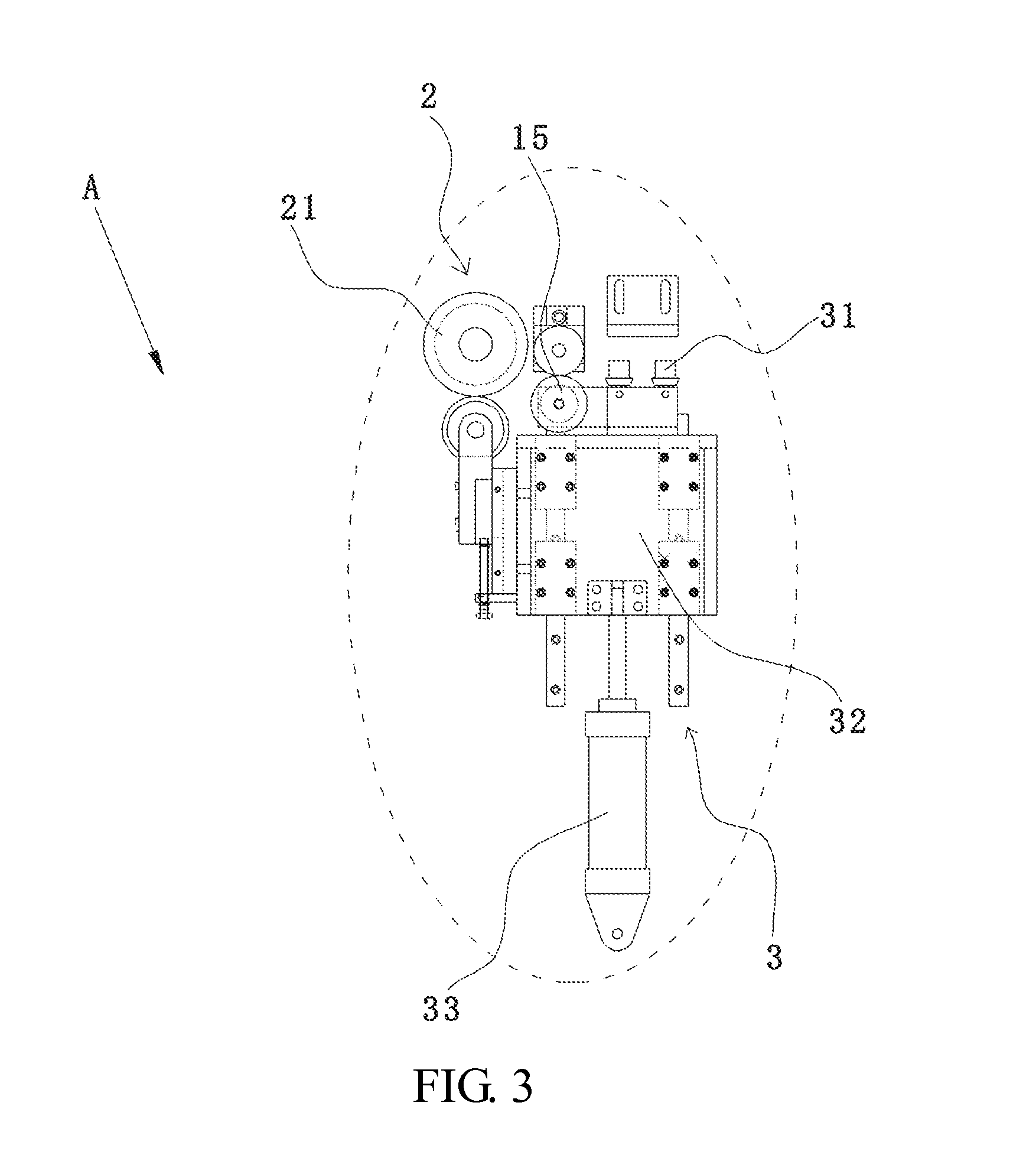
[0028]FIG. 1 is a front view showing an automatic canvas wrapping machine according to one embodiment of the present invention. FIG. 2 is a top view showing the automatic canvas wrapping machine shown in FIG. 1. FIG. 3 is an enlarged diagram of A in the automatic canvas wrapping machine shown in FIG. 1. FIG. 4 is a front view showing an automatic canvas wrapping machine according to another embodiment of the invention. FIG. 5 is a top view showing the automatic canvas wrapping machine shown in FIG. 4. Please refer to FIG. 1 to FIG. 5 together.

[0029]As shown in FIG. 1, the automatic canvas wrapping machine in the embodiment includes a canvas conveying device 1, a yarn core mounting device 2, a canvas wrapping device 3, and a cutting device 4. The canvas conveying device 1 conveys a rubberized canvas for wrapping a yarn core. The yarn core mounting device 2 is disposed in a conveying direction of the canvas conveying device 1, and the yarn core is mounted in the yarn core mounting dev...


PUM

PropertyMeasurementUnit
Distanceaaaaaaaaaa

Abstract

An automatic canvas wrapping machine including a canvas conveying device, a yarn core mounting device, a canvas wrapping device, and a cutting device is described herein. The canvas conveying device conveys a rubberized canvas for wrapping a yarn core. The yarn core mounting device is disposed in a conveying direction of the canvas conveying device, and the yarn core is mounted in the yarn core mounting device and attached to the rubberized canvas conveyed by the canvas conveying device. The canvas wrapping device is disposed on one side of the yarn core mounting device and presses the rubberized canvas reciprocatingly along a direction vertical to the conveying direction, so as to tightly attach the rubberized canvas to the yarn core. The cutting device is disposed at an upper part of the canvas conveying device and cuts the rubberized canvas after the canvas wrapping device completes canvas wrapping.

Description

CROSS-REFERENCE TO RELATED APPLICATIONS[0001]This Non-provisional application claims priority under 35 U.S.C. §119(a) on Patent Application No(s). 201410599616.5 filed in People's Republic of China on Oct. 31, 2014, the entire contents of which are hereby incorporated by reference.BACKGROUND OF THE INVENTION[0002]1. Field of the Invention[0003]The present invention belongs to a manufacturing technical field of a drive belt molding apparatus and, more particularly, relates to an automatic canvas wrapping machine.[0004]2. Description of the Related Art[0005]A drive belt is a device for transferring power generated by rotation of a motor or an engine of a prime mover to mechanical apparatus through a rubber belt via a belt pulley. The drive belt is widely applied in the fields of motors, agricultural machines, machine tools, automobiles, ships, household appliances, office equipment and so on. The drive belt has the advantages of free speed change, far and near driving, simple structur...

Claims


Application Information

Patent Timeline
IPC IPC(8): B29D29/00
CPCB29D29/00B29D29/10
Inventor WU, PEISHENGSHI, SHUIXIANGZHU, XINFUWU, LIXIANG
Owner SANLUX
Why Eureka
Try Eureka