Rapid charging power supply system

Inactive Publication Date: 2016-05-05
INST FOR ENERGY APPL TECH
View PDF4 Cites 45 Cited by
  • Summary
  • Abstract
  • Description
  • Claims
  • Application Information

AI Technical Summary

Benefits of technology

[0017]According to the invention defined by claim 1, the rapid charging power supply system is able to perform rapid charging on the first electric moving body with DC power supplied from the stationary electric storage means, and is able to perform rapid charging on the second electric moving body with DC power supplied from the stationary electric storage means through the second stationary rapid charger.
[0018]Accordingly, it becomes possible to rapidly charge both of the first electric moving body and the second electric moving body at the same time, even if such a traffic society comes to exist in which the first electric moving bodies and second electric moving bodies of different charging methods are mixed and used, it becomes possible to perform rapid charging on the respective electric moving body smoothly without causing confusion.
[0019]According to the invention defined by claim 1, during the charging of the first electric moving body or second electric moving body with DC power output from the stationary electric storage means, the power feeding control means discontinues power feeding from the first stationary rapid charger to the stationary electric storage means. Accordingly, if the power supply is a commercial AC power supply, rapid charging can be performed on the first electric moving body and second electric moving body with only the electric power stored in the stationary electric storage means without causing excessive burden on energy transmission and distribution systems of electric power companies.
[0020]Accordingly, upon rapid charging of the respective electric moving bodies, maximum electric po

Problems solved by technology

While electric vehicles are excellent from an environmental point of view since they do not rele

Method used


Image

  • Rapid charging power supply system
  • Rapid charging power supply system
  • Rapid charging power supply system

Examples


Example

Embodiment 1

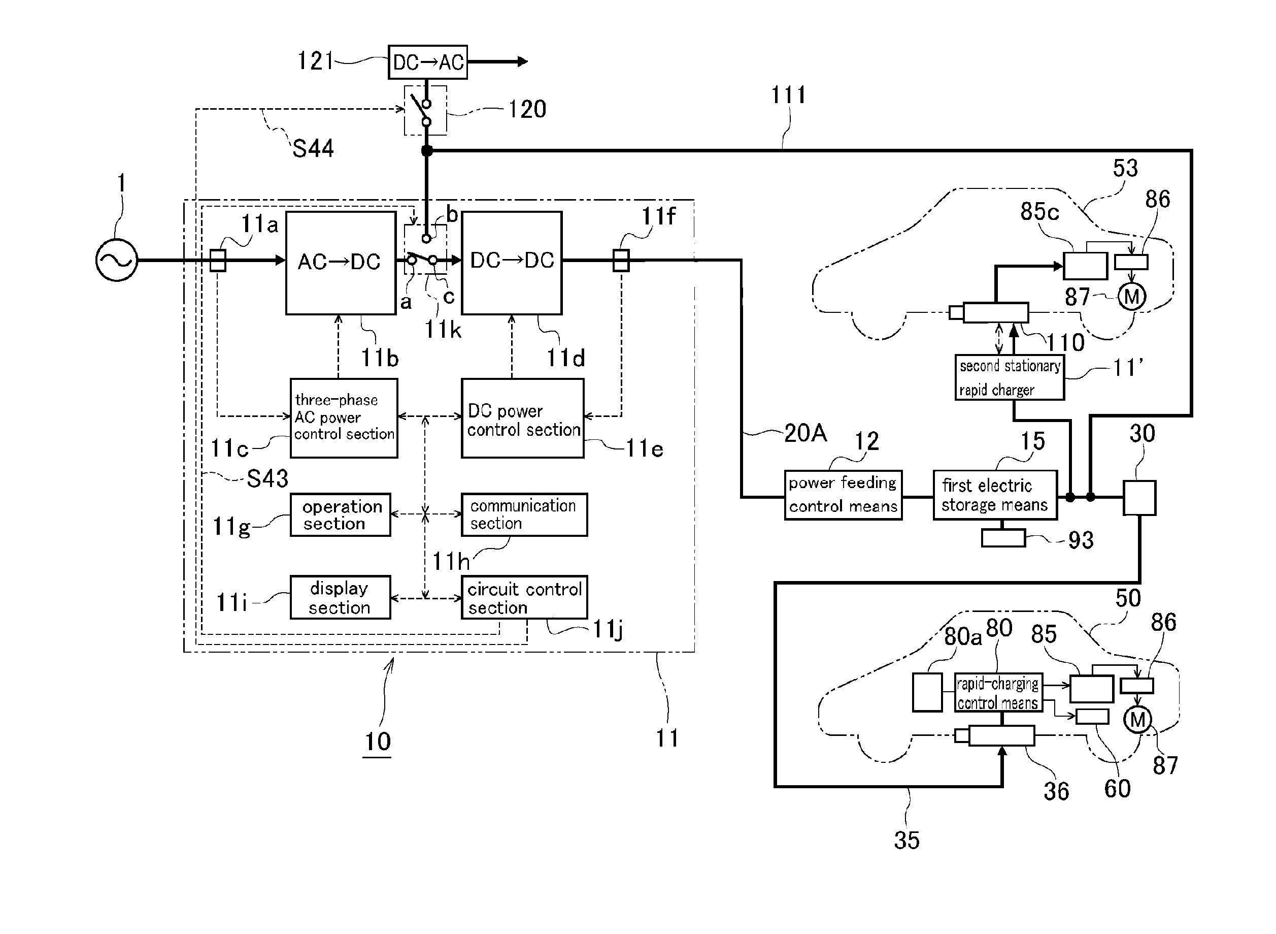
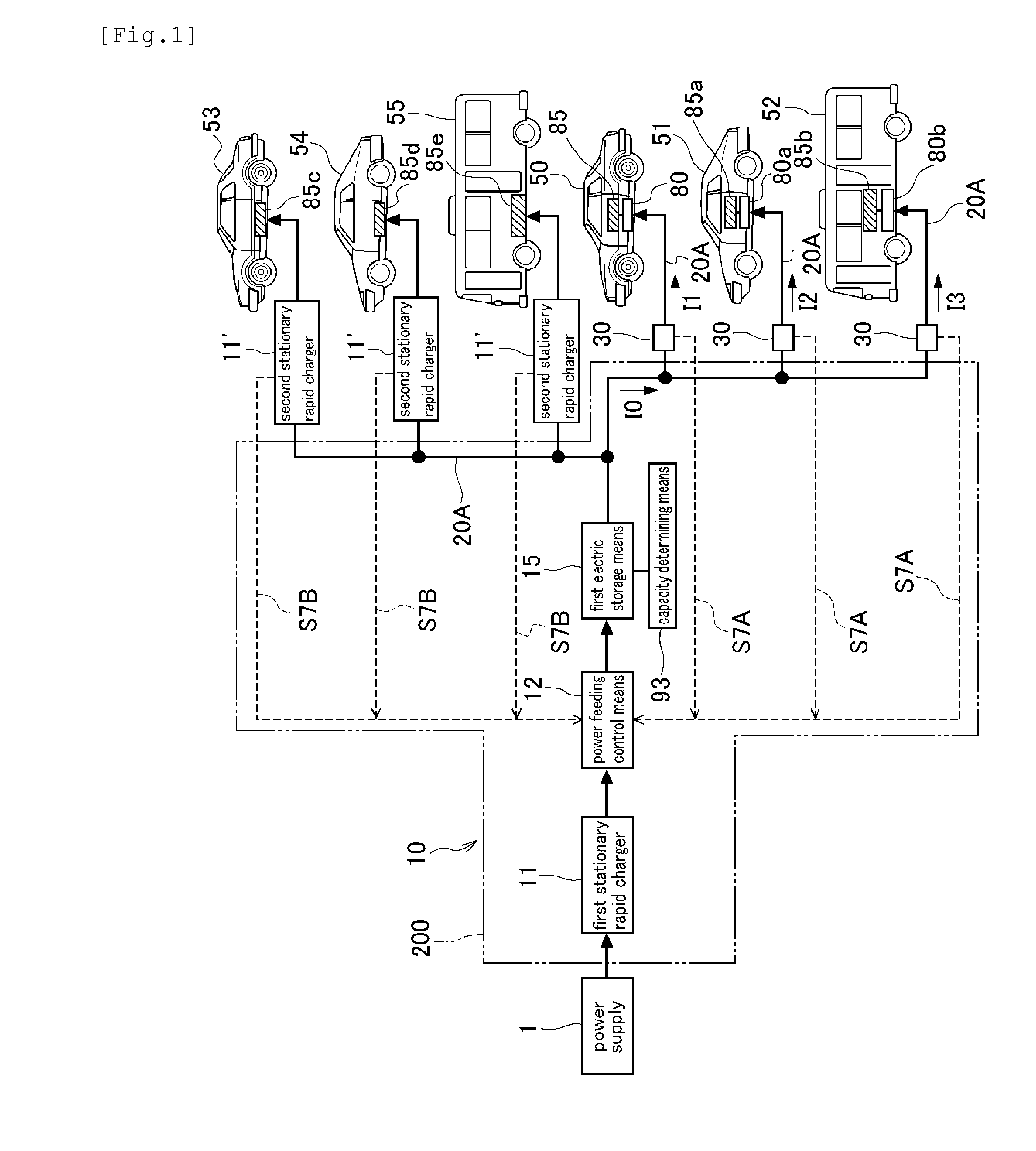
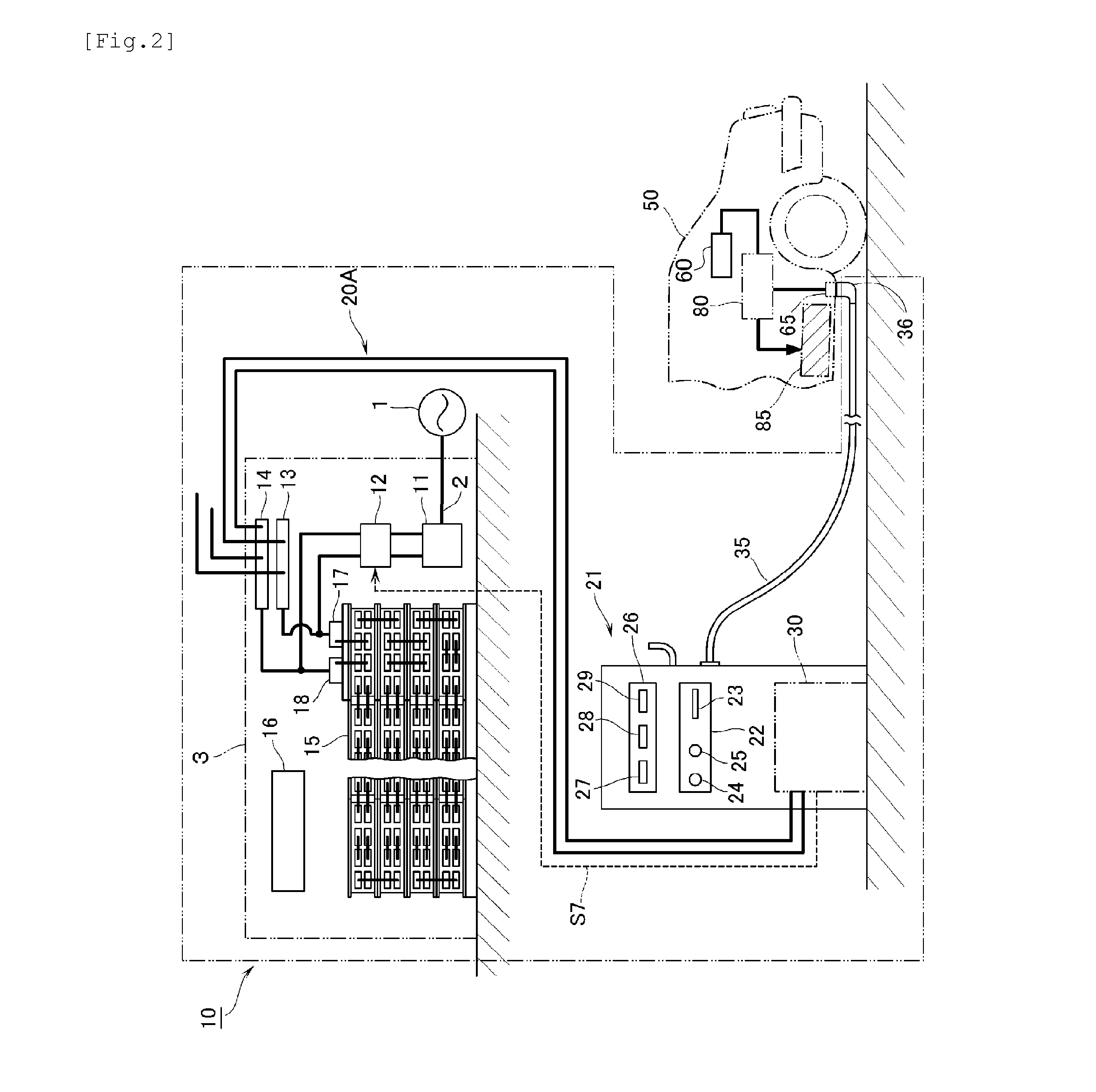
[0050]FIGS. 1 to 12 show Embodiment 1 according to the present invention. In FIG. 2, reference numeral 1 indicates a commercial AC power supply as a power source, and a three-phase AC power supply, for example, is used as an AC power supply 1. Power from the AC power supply 1 is supplied into a building 3 through an electric power line 2. Within the building 3, there are a first stationary rapid charger 11, a power feeding control means 12, a first electric storage means 15 functioning as a stationary electric storage means, and other devices, which constitute a rapid charging power supply system 10. The input side of the first stationary rapid charger 11 is connected to the electric power line 2 within the building 3. The first stationary rapid charger 11 has a function of regulating three-phase AC power from the electric power line 2 to a predetermined voltage value, and converting it into DC power. The output side of the first stationary rapid charger 11 is connected ...

Example

Embodiment 2

[0090]FIG. 13 shows Embodiment 2 according to the present invention, showing a case of application for rapid charging with electric power obtained by using renewable energy. The difference in Embodiment 2 from Embodiment 1 is the difference in the power supply used for rapid charging, and the remaining parts correspond to Embodiment 1. Accordingly, the same reference numerals as those in Embodiment 1 are denoted for the corresponding parts, thus omitting the description with respect to the corresponding parts. The same applies to other embodiments to be described below.

[0091]Electric power generation utilizing renewable energy such as wind power or solar light is excellent for environment since such generation does not produce CO2 during the generation of electric power. However, such wind power generation and solar power generation are susceptible to weather, and the output is greatly varied, thus having a problem of being difficult to be in cooperation with electric po...

Example

Embodiment 3

[0093]FIGS. 14 and 15 show Embodiment 3 according to the present invention. The difference in Embodiment 3 from Embodiment 1 is only the presence or absence of a power supply switching means 11m in a first stationary rapid charger 11. In Embodiment 3, with regard to rapid charging of vehicles 53 to 55 as second electric moving bodies with no rapid-charging control means 80 equipped therein, the rapid charging can be performed by using only a first stationary rapid charger 11, without a first electric storage means 15 or a second stationary rapid charger 11′.

[0094]As shown in FIG. 14, the power supply switching means 11m is connected with the output side of the power supply switching means 11m. In Embodiment 3, as shown in FIG. 15, the power supply switching means 11m is integrated with the first stationary rapid charger 11. The power supply switching means 11m is constituted of a first fixed contact point a, a second fixed contact point b, and a moving contact c. The mov...


PUM


Abstract

Embodiments of the disclosed technology are directed to a rapid charging power supply system capable of rapidly charging an electric moving body, such as a vehicle. Certain example embodiments are directed to a rapid charging power supply system capable of rapidly charging two electric moving bodies with different charging methods at the same time using a single system. For example, a rapid charging power supply system capable of rapid charging, using a single system, both an electric moving body having a rapid-charging control means equipped therein and an electric moving body that does not have a rapid-charging control means equipped therein is provided.

Description

TECHNICAL FIELD[0001]The present invention is directed to a rapid charging power supply system capable of rapidly charging an electric moving body, such as a vehicle, and in particular, the present invention is directed to a rapid charging power supply system capable of rapidly charging two electric moving bodies of different charging methods at the same time using a single system.BACKGROUND ART[0002]While electric vehicles are excellent from an environmental point of view since they do not release exhaust gas, they have a problem of requiring a relatively long period of time for charging. In order to shorten the charging time, it is necessary to supply a large amount of power in a short period of time to electric vehicles; and it is necessary for an area in which only low voltage power lines are laid to increase the power reception capacity of the electric power facilities. Accordingly, there is a technique known to rectify commercial AC power, to store DC power in a large-size sto...

Claims


Application Information

Patent Timeline
IPC IPC(8): B60L11/18
CPCB60L11/1818B60L11/185B60L3/00B60L2200/10B60L2200/18B60L2200/26B60L2200/36B60L2200/42Y02T90/14Y04S30/14Y02P90/60B60L53/16B60L53/65B60L53/11B60L53/305B60L53/51B60L53/52B60L53/54B60L53/53H02J7/342B60L53/67B60L58/26B60L58/18H02J2310/48Y02T10/70Y02T10/7072Y02T90/12Y02T90/16Y02T90/167H02J7/0013H02J3/32
Inventor SUGANO, TOMIO
Owner INST FOR ENERGY APPL TECH
Why Eureka
Try Eureka