Copper alloy wire

Active Publication Date: 2016-05-05
MITSUBISHI MATERIALS CORP
2 Cites 1 Cited by

AI-Extracted Technical Summary

Problems solved by technology

In recent years, the travelling speed of a train has been increasing; however, when, in a high-speed railway such as Shinkansen, the travelling speed of a train becomes faster than the propagation speed of a wave generated in an over...

Method used

[0056]Sn is an element having an action in which Sn forms a solid solution in the matrix phase of copper so as to improve the strength. In addition, Sn also has an effect of accelerating the precipitation of a precipitate containing Co and P as main components and an action of improving thermal resistance and corrosion resistance.
[0059]The amount of Sn is more desirably in a range of more than or equal to 0.15 mass % and less than or equal to 0.3 mass %. In this range, it is possible to obtain a favorable strength-conductivity balance. Meanwhile, in a case in which the amount of Sn is set to be in a range of more than or equal to 0.3 mass % and less than or equal to 0.5 mass %, it is possible to significantly improve the strength.
[0061]As described above, Co and P form the precipitate made of the complex of Co and P and thus contribute to precipitation hardening. Meanwhile, Sn forms a solid solution in the matrix phase and thus contributes to solid solution hardening. Therefore, it becomes possible to optimize the balance between precipitation hardening and solid solution hardening by controlling (Co+P)/Sn.
[0092]According to the copper alloy wire having the above-described constitution, which is the present embodiment, since the copper alloy wire includes relatively large amounts of Co and P (Co: more than or equal to 0.20 mass % and less than or equal to 0.35 mass % and P: more than 0.095 mass % and less than or equal to 0.15 mass %), even in a case in which the copper alloy wire is manufactured using the continuous cast-rolling device shown in ...

Benefits of technology

[0029]According to the present invention, it becomes possible to provide a copper alloy wire which is made of a precipitation hardening-type copper alloy containing Co, P, and Sn and is capable o...

Abstract

This copper alloy wire is a copper alloy wire which is made of a precipitation hardening-type copper alloy containing Co, P, and Sn and is manufactured using a continuous cast-rolling method or cold working of a continuous cast wire rod manufactured using a continuous casting method, in which the copper alloy wire has a composition including Co: more than or equal to 0.20 mass % and less than or equal to 0.35 mass %, P: more than 0.095 mass % and less than or equal to 0.15 mass %, and Sn: more than or equal to 0.01 mass % and less than or equal to 0.5 mass % with a balance being Cu and inevitable impurities.

Application Domain

Conductive materialMetal rolling arrangements

Technology Topic

PrecipitationCopper alloy +5

Image

  • Copper alloy wire
  • Copper alloy wire
  • Copper alloy wire

Examples

  • Experimental program(6)

Example

Example 1
Examples of Present Invention 1 to 13 and Comparative Examples 1 to 5
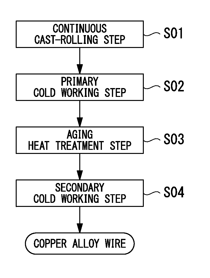
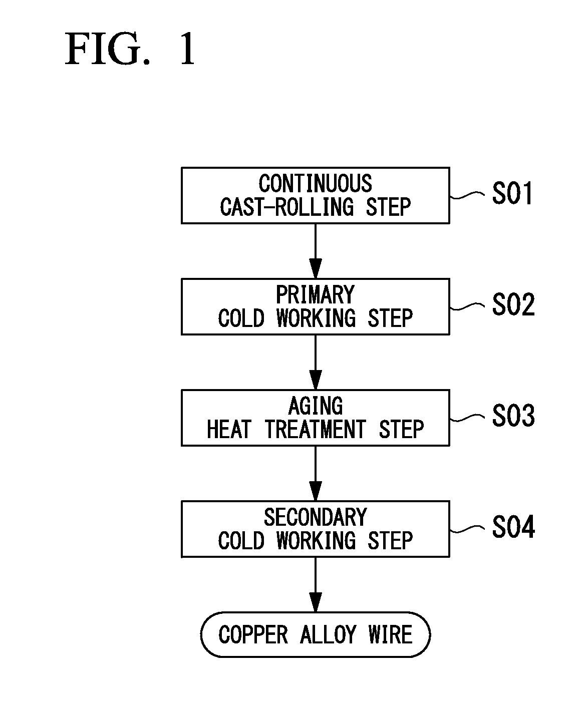
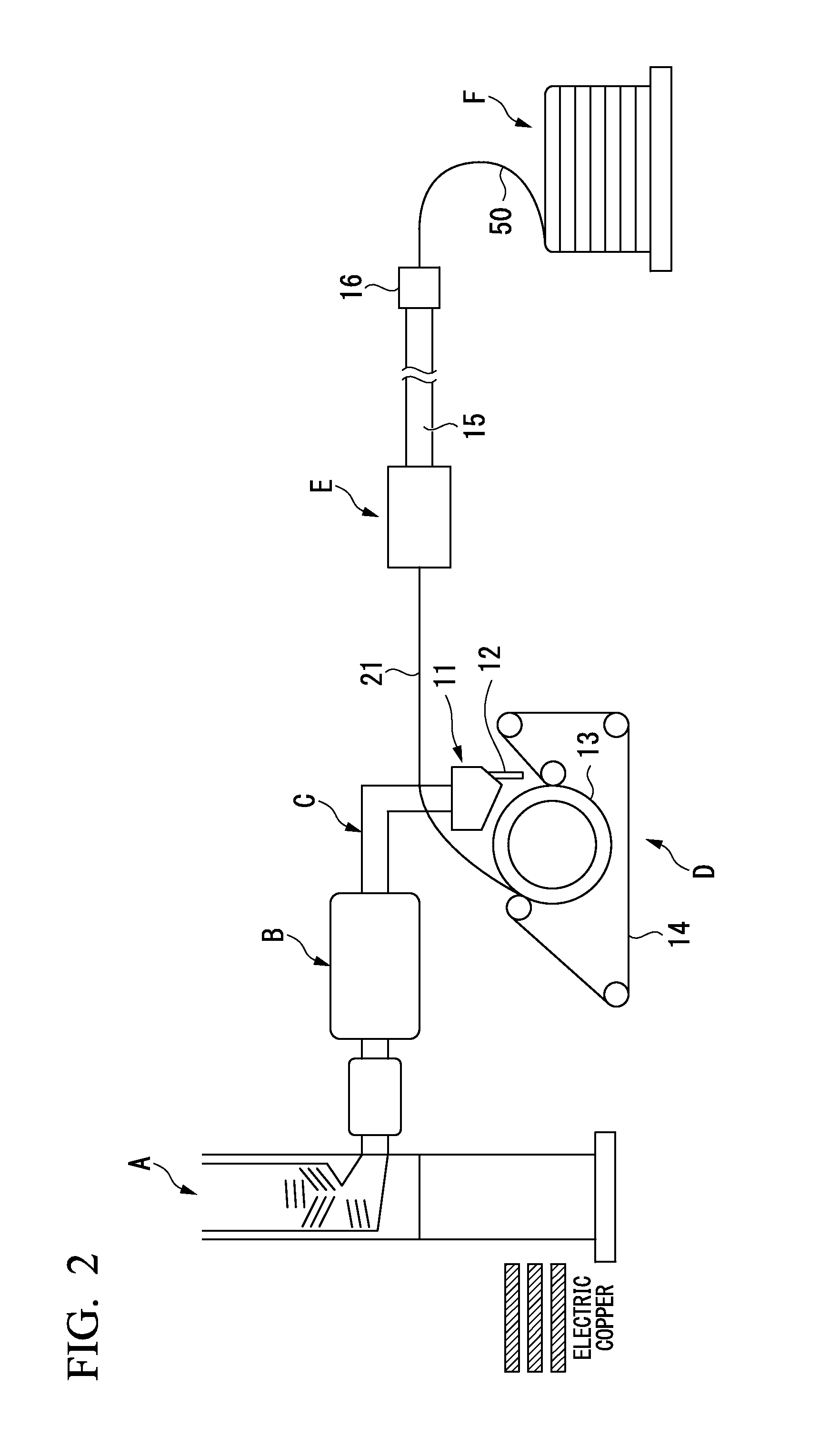
[0102]Copper wire rods (with an outer diameter of 25 mm) made of a copper alloy having a composition shown in Table 1 were produced using a continuous cast-rolling facility provided with a belt wheel-type continuous caster. Primary cold working was carried out on these copper wire rods so as to reduce the outer diameter to 18 mm, and then an aging heat treatment was carried out under conditions shown in Table 2. After that, secondary cold working was carried out, thereby reducing the outer diameter to 12 mm.
Conventional Example
[0103]A billet having an outer diameter of 240 mm made of a copper alloy having a composition shown in Table 1 was prepared, and was reheated to 950° C., thereby carrying out hot extrusion. Primary cold working was carried out on the obtained extruded material so as to reduce the outer diameter to 18 mm, and then an aging heat treatment was carried out under conditions shown in Table 2. After that, secondary cold working was carried out, thereby reducing the outer diameter to 12 mm.
[0104]The tensile strengths and conductivities of the copper alloy wires obtained as described above were evaluated as described below.
[0105]The tensile strength was measured by carrying out a tensile test using an AG-100kNZ manufactured by Shimadzu Corporation according to JIS Z 2241 (in conformity with ISO 6892-1). The results are shown in Table 2.
[0106]The conductivity was measured using a double bridge method according to JIS H 0505. In detail, the conductivity was obtained by measuring the electrical resistance of a test specimen having an outer diameter of 12 mm and a length of 350 mm at 20° C. using a double bridge-type resistance measurement instrument (275200 manufactured by Yokogawa Electric Corporation), computing the conductance using an average section method, and expressing the percentage of the conductance with respect to the conductance of the standard annealed copper (the standard annealed copper regulated by International Electrotechnical Commission (ICE)).
[0107]The evaluation results are shown in Table 2.
[0108]In addition, in the Conventional Example, a 5 mm×5 mm observation specimen was taken from the sectional center portion of the hot extruded material obtained through hot extrusion, and the line analyses of Co and P were carried out through EPMA analyses.
[0109]The results are shown in FIG. 3.
[0110]Furthermore, in Example of Present Invention 1, a 5 mm×5 mm observation specimen was taken from the sectional center portion of an intermediate rolled material in the continuous cast-rolling step, and the line analyses of Co and P were carried out through EPMA analyses.
[0111]The results are shown in FIG. 4.
TABLE 1 Alloy component composition Co P Sn Co/P (Co + P)/Sn Ni Fe Zn Mg Ag Zr mass mass mass Atomic Atomic mass mass mass mass mass mass % % % ratio ratio % % % % % % Cu Examples 1 0.251 0.109 0.063 1.210 14.658 — — — — — — Balance of Present 2 0.248 0.106 0.081 1.230 11.184 — — — — — — Balance Invention 3 0.267 0.107 0.090 1.311 10.533 — — — — — — Balance 4 0.236 0.136 0.053 0.912 18.806 — — — — — — Balance 5 0.318 0.097 0.086 1.723 11.772 — — — — — — Balance 6 0.311 0.133 0.081 1.229 14.028 0.041 — 0.048 — — — Balance 7 0.242 0.099 0.039 1.285 22.230 0.144 0.049 — 0.160 — — Balance 8 0.229 0.096 0.047 1.254 17.644 0.138 0.030 — — 0.236 — Balance 9 0.297 0.128 0.057 1.219 19.104 — 0.065 — — — 0.027 Balance 10 0.215 0.103 0.412 1.100 2.030 — — — — — — Balance 11 0.220 0.137 0.462 0.846 2.117 — — — — — — Balance 12 0.342 0.100 0.473 1.802 2.291 — — — — — — Balance 13 0.338 0.141 0.470 1.263 2.626 — — — — — — Balance Comparative 1 0.185 0.107 — 0.909 — — — — — — — Balance Examples 2 0.263 0.087 — 1.589 — — — — — — — Balance 3 0.307 0.156 — 1.034 — — — — — — — Balance 4 0.311 0.113 0.005 1.446 211.924 — — — — — — Balance 5 0.264 0.103 0.631 1.347 1.468 — — — — — — Balance Conventional 0.278 0.084 0.041 1.739 21.512 0.046 — 0.017 — — — Balance Example
TABLE 2 Step Evaluation Aging heat treatment Tensile Temperature Time strength Conductivity ° C. min. MPa % IACS Example 1 Continuous cast-rolling 500 4 564 80 of Present 2 Continuous cast-rolling 500 4 565 80 Invention 3 Continuous cast-rolling 500 4 565 81 4 Continuous cast-rolling 500 4 559 79 5 Continuous cast-rolling 500 4 554 79 6 Continuous cast-rolling 500 4 567 79 7 Continuous cast-rolling 500 4 566 80 8 Continuous cast-rolling 500 4 568 80 9 Continuous cast-rolling 500 4 570 79 10 Continuous cast-rolling 500 4 568 77 11 Continuous cast-rolling 500 4 570 77 12 Continuous cast-rolling 500 4 581 76 13 Continuous cast-rolling 500 4 584 77 Comparative 1 Continuous cast-rolling 500 4 515 76 Examples 2 Continuous cast-rolling 500 4 524 78 3 Continuous cast-rolling 500 4 566 69 4 Continuous cast-rolling 500 4 530 81 5 Continuous cast-rolling 500 4 580 63 Conventional Hot extrusion 500 4 565 81 Example
[0112]In Comparative Examples 1 and 2 in which the contents of Co and P were smaller than the range of the present invention, the tensile strengths were insufficient. This was assumed to be because the precipitates of Co and P were not sufficiently dispersed.

Example

[0113]In Comparative Example 3 in which the contents of Co and P were greater than the range of the present invention, the conductivity was low.

Example

[0114]In Comparative Example 4 in which the amount of Sn was smaller than the range of the present invention, the tensile strength was insufficient. This was assumed to be because the solid solution hardening by Sn was insufficient.

PUM

PropertyMeasurementUnit
Percent by mass0.2mass fraction
Percent by mass0.35mass fraction
Percent by mass0.095mass fraction

Description & Claims & Application Information

We can also present the details of the Description, Claims and Application information to help users get a comprehensive understanding of the technical details of the patent, such as background art, summary of invention, brief description of drawings, description of embodiments, and other original content. On the other hand, users can also determine the specific scope of protection of the technology through the list of claims; as well as understand the changes in the life cycle of the technology with the presentation of the patent timeline. Login to view more.

Similar technology patents

Wind Turbine Rotor Blade with Varying Blade Depth

InactiveUS20120219423A1great thicknesssufficient strength
Owner:NORDEX ENERGY

Method of net-forming an article and apparatus for same

ActiveUS20070240480A1sufficient strengthimprove work flow
Owner:GM GLOBAL TECH OPERATIONS LLC

Flywheel

InactiveUS20120111142A1sufficient strengthsuitable stiffness
Owner:RICARDO UK LTD

Modular toy vehicle accessory mounts

InactiveUS20080254708A1sufficient strength
Owner:RIDEMAKERZ

Classification and recommendation of technical efficacy words

  • sufficient strength
  • ensure strength

Electronic component mounting package and package assembled substrate

InactiveUS20060220205A1large mount areasufficient strength
Owner:SANYO ELECTRIC CO LTD

Conduit, manufacture thereof and fusion process therefor

InactiveUS20080257604A1sufficient strengthpreclude leakage
Owner:UNDERGROUND SOLUTIONS TECH GROUP

Bracket for Orthodontic

InactiveUS20090220907A1sufficient strengthnot be thin
Owner:SUYAMA HAJIME

Rotor for rotating electric machine

ActiveUS20150137650A1high strengthensure strength
Owner:DENSO CORP

Gas sensor element

ActiveUS20180017514A1ensure strength
Owner:TOYOTA JIDOSHA KK +1

Planetary carrier and method for manufacturing the same

ActiveUS20210088125A1ensure strengthdecrease in size
Owner:AISIN AW CO LTD
Why Eureka
Try Eureka