Cutting edge attachment for snow plow

a technology for snow plows and cutting edges, which is applied in snow cleaning, way cleaning, construction, etc., can solve the problems of prolonging the life of equipment, becoming very expensive to repair if repairable at all, and reducing the service life of equipment, so as to improve service life and reduce the cost. , the effect of improving the service li

Active Publication Date: 2016-05-05
NORDIC AUTO PLOW
View PDF27 Cites 1 Cited by
  • Summary
  • Abstract
  • Description
  • Claims
  • Application Information

AI Technical Summary

Benefits of technology

[0014]The rounded cutting edge of this invention, which is readily attachable to existing mold boards, is more efficient and less costly than those set forth in the previously mentioned patent documents. In an embodiment of this invention, the rounded cutting edge is molded to form a solid, one piece section, such that welded mounting brackets are not required. The rounded edge of this invention is made in various thicknesses and sizes, to accommodate the standard plow mold boards now available. The rounded cutting edge is provided in various lengths, widths and thicknesses and bolt hole patterns to accommodate the standard plow mold boards now available. The rounded cutting edge of this invention when formed of composite material and attached directly to a traditional cutting edge, will wear at a much slower pace than other composite material plows now available. A rounded cutting edge of this invention formed of composite material when attached directly to a traditional cutting edge, will wear at a much slower pace than other composite material plows on the market. The rounded cutting edge of this invention when formed of a composite material will wear at the same pace as the steel cutting edge behind it, thus requiring less frequent replacement, saving the user the cost of more frequent replacement and still providing the benefits of less vibration, less road and ground damage, and less wear and tear on the plow blade and vehicle.

Problems solved by technology

Once a mold board is bent, it becomes very expensive to repair if repairable at all.
The rubber or poly composite material edges are molded and have a petroleum base, which makes them more expensive than traditional steel edges.
The rounded cutting edge will generate less friction than traditional edges and thus will cause less vibration to the plow blade and vehicle, thus prolonging the life of the equipment.
It is difficult to drill holes in hardened steel.
The walls of the rounded tube in both the Borowiak patent and the Wrightman published application must be made of steel since round tubes of any polymer, or rubber based composite material would quickly wear or collapse under the weight of the plow.
Furthermore, in real life usage, a safety hazard exists in both designs, because once the bottom edge of the cylinder wears through, the front edge of the cylinder will completely dislodge and fall off.
When this happens, the strip will ricochet like flying shrapnel that could hit pedestrians, damage vehicles and cause accidents.
Further, the arrangements of both Borowiak and Wrightman will lose any advantage a rounded edge affords as soon as the bottom edge wears through, instantly turning the bottom edge of the blade into a vibrating sharp edge with flapping material.
Holes must be cut into the traditional cutting edge, which can be extremely difficult when the edge is made of hardened steel.

Method used


Image

  • Cutting edge attachment for snow plow
  • Cutting edge attachment for snow plow
  • Cutting edge attachment for snow plow

Examples


first embodiment

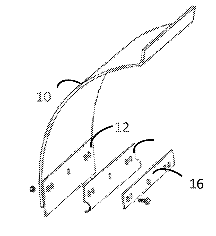
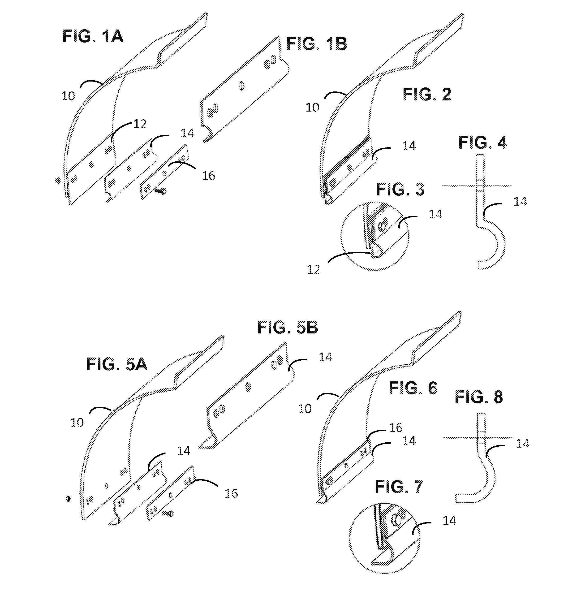
[0035]Referring to FIGS. 1A through 4, a first preferred embodiment of this invention will be described. FIG. 1A shows a customary plow blade mold board 10, and a traditional cutting edge blade 12, both of which are provided with mounting holes of a standard pattern for a particular type of plow mold board. A rounded cutting edge 14 in accordance with this invention is shown spaced from the traditional cutting edge blade 12. The rounded cutting edge has a flat upper section and a lower curved section with a 180 degree radius. A reinforcing plate 16 is shown spaced from the rounded cutting edge 14. Both the rounded cutting edge 14 and the reinforcing plate 16 are provided with mounting holes conforming to the standard pattern of the plow mold board on which they are mounted. As shown in FIG. 2, the rounded cutting edge 14 and the reinforcing plate 16 are secured to the plow blade mold board 10, the traditional cutting edge blade 12, by fastening devices shown as bolts. The bolts, one...

second embodiment

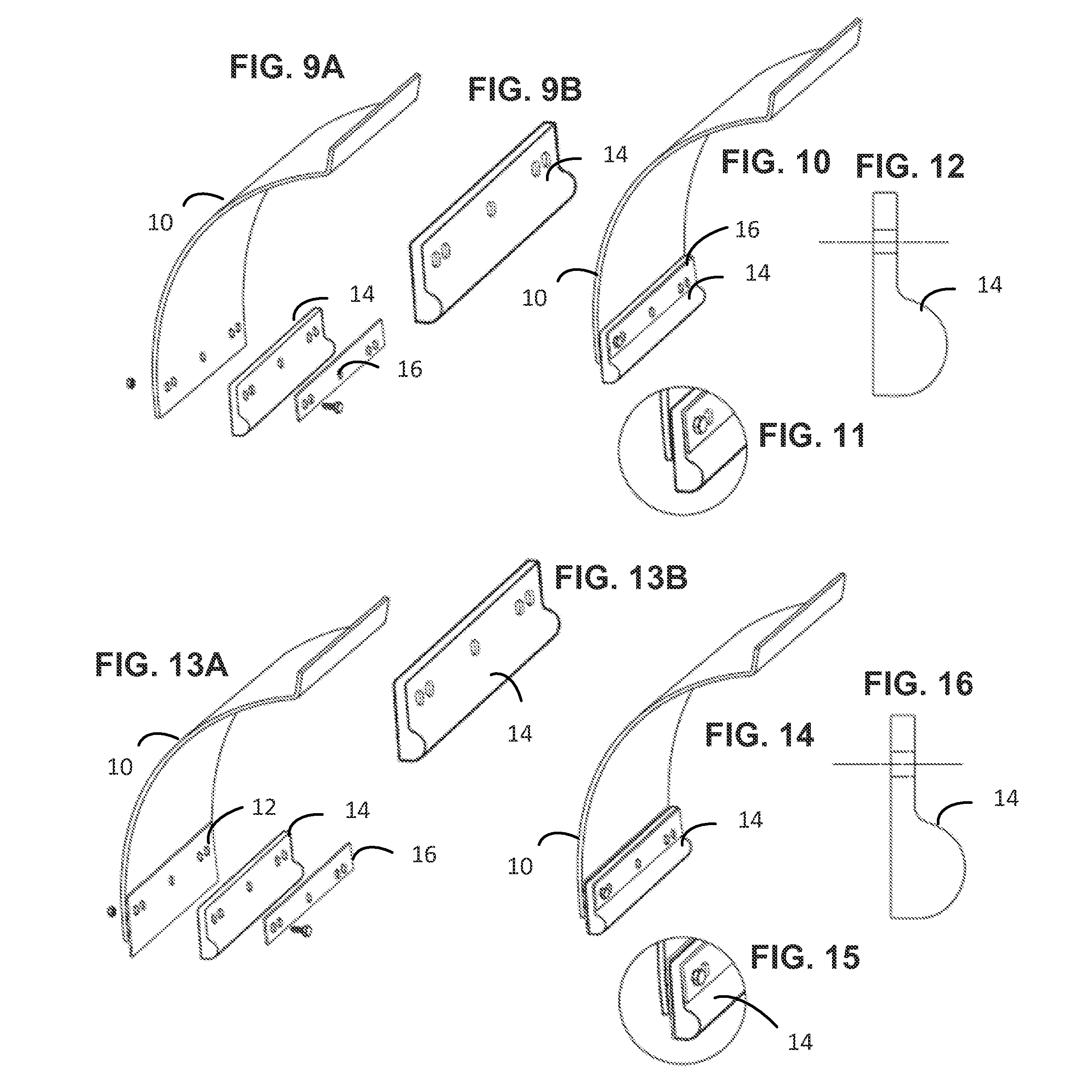
[0037]Referring to FIGS. 9A through 12, a second preferred embodiment of this invention will be described. FIG. 9A shows a customary plow blade mold board 10, with the traditional cutting edge blade removed. A rounded cutting edge 14 in accordance with this invention is shown spaced from the plow mold board 10. A reinforcing plate 16 is shown spaced from the rounded cutting edge 14. As shown in FIG. 14, the rounded cutting edge 14 and the reinforcing plate 16 are secured to the plow blade mold board 10, by fastening devices shown as bolts. The bolts pass through holes previously provided in the plow blade mold board 10 for mounting the traditional replaceable cutting edge blade 12. As best shown in the enlarged end view of FIG. 11, the free end of the rounded cutting edge 14 extends below the lower edge of the plow mold board 10. Enlarged perspective and end views of the rounded cutting edge 14 are shown in FIGS. 9B and 12. In this second embodiment of the invention, the rounded cut...

fourth embodiment

[0038]Referring to FIGS. 13A through 16, a fourth preferred embodiment of this invention will be described. FIG. 13A shows a customary plow blade mold board 10, and a traditional cutting edge blade 12. A rounded cutting edge 14 in accordance with this invention is shown spaced from the traditional cutting edge blade 12. A reinforcing plate 16 is shown spaced from the rounded cutting edge 14. As shown in FIG. 14, the rounded cutting edge 14 and the reinforcing plate 16 are secured to the plow blade mold board 10, the traditional cutting edge blade 12, by fastening devices shown as bolts. The bolts pass through holes previously provided in the plow blade mold board 10 for mounting the replaceable traditional cutting edge blade 12. As best shown in the enlarged end view of FIG. 15, the lower end of the rounded cutting edge 14 is aligned with the lower edge of the traditional cutting edge blade 12. Enlarged perspective and end views of the rounded cutting edge 14 are shown in FIGS. 13B ...


PUM


Abstract

The present invention relates to a rounded edge “cutting edge” blade that attaches either directly to the bottom of a plow blade mold board or that attaches to the front side of a traditional cutting edge blade that is already mounted to the mold board using the existing mounting bolts and holes already present. The rounded edge of the blade, when making contact with the ground surface, will not get caught on cracks or irregular surfaces. The rounded edge can be made of steel, polyurethane, rubber or other appropriate composite material and the thickness can vary depending upon the blade and vehicle being mounted to.

Description

BACKGROUND OF THE INVENTION AND PRIOR ART[0001]The present invention relates to a rounded edge “cutting edge” blade that attaches either directly to the bottom of a plow blade mold board or which attaches to the front side of a traditional cutting edge blade that is already mounted to the mold board using the existing mounting bolts and holes. The rounded edge of the blade, when making contact with the ground surface, does not get caught on cracks or irregular surfaces.[0002]Snow plows consist of the main body of a plow, known as a mold board, and replaceable cutting edges that make contact to the ground surface. Cutting edges protect the plow from being dented or bent as it scrapes along irregular ground surface. Once a mold board is bent, it becomes very expensive to repair if repairable at all. Currently cutting edges come in various widths, heights and thicknesses to fit the plow blades on the market ranging from 4 to 12 ft wide, 4 to 10 inches tall, and 0.50 to 3 inches thick, ...

Claims


Application Information

Patent Timeline
Patent Type & Authority Applications(United States)
IPC IPC(8): E01H5/06
CPCE01H5/061
Inventor BEHAN, RICHARD ANTHONYBEHAN, PAULETTE SANDERS
Owner NORDIC AUTO PLOW
Why Eureka
Try Eureka