Method to provide a quality measure for meter verification results

a flowmeter and quality measurement technology, applied in the field of flowmeter systems and methods, can solve the problems of corrosive flowmeters, abrasives, caustic, and out-of-date calibration data,

Active Publication Date: 2016-05-05
SCHNEIDER ELECTRIC SYST USA INC
View PDF6 Cites 11 Cited by
  • Summary
  • Abstract
  • Description
  • Claims
  • Application Information

AI Technical Summary

Problems solved by technology

In some applications, the fluid flowing through a Coriolis flowmeter is corrosive, abrasive, caustic, etc.
Such fluids and/or other environmental conditions can cause a flowtube to become damaged through wear or other breakage.
However, when the physical properties of the flowtube change, the calibration data becomes out of date, and the measurement system can produce inaccurate measurements.
Thus, normal wear on the...

Method used


Image

  • Method to provide a quality measure for meter verification results
  • Method to provide a quality measure for meter verification results
  • Method to provide a quality measure for meter verification results

Examples


Embodiment Construction

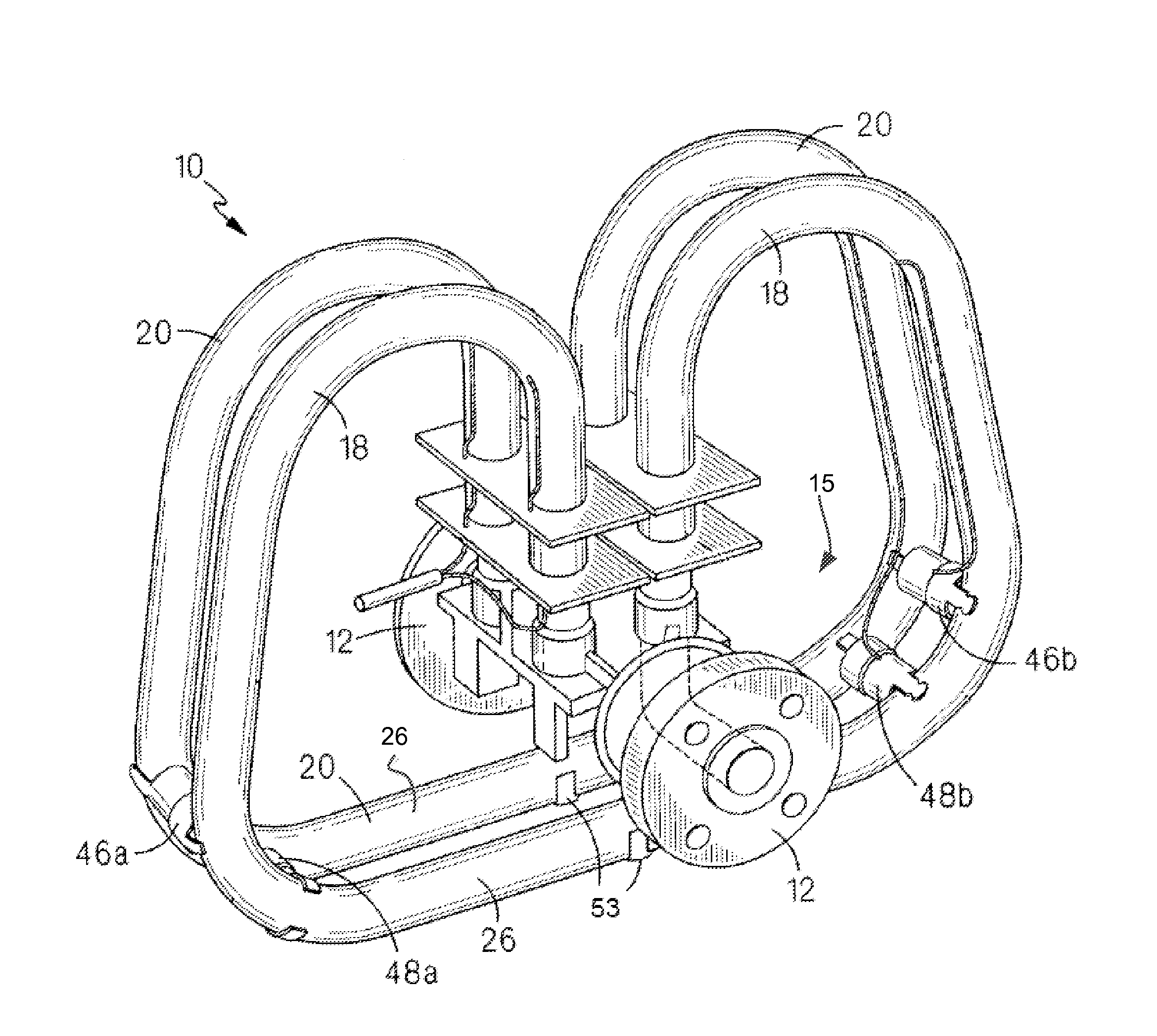
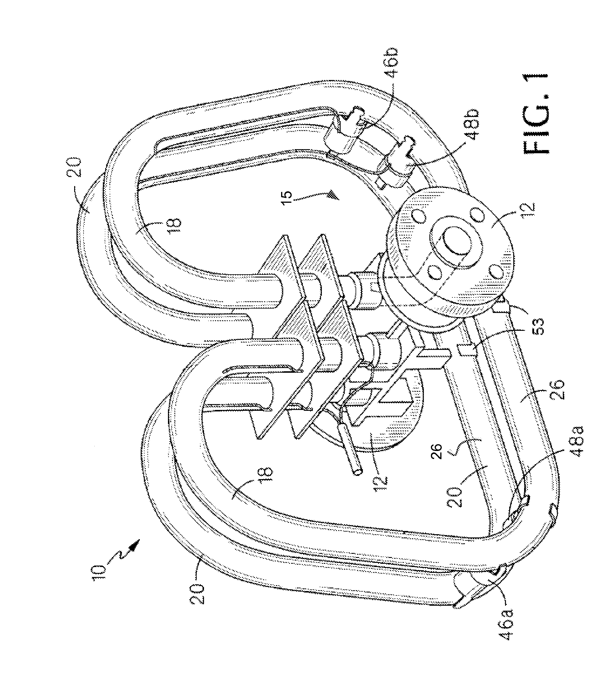
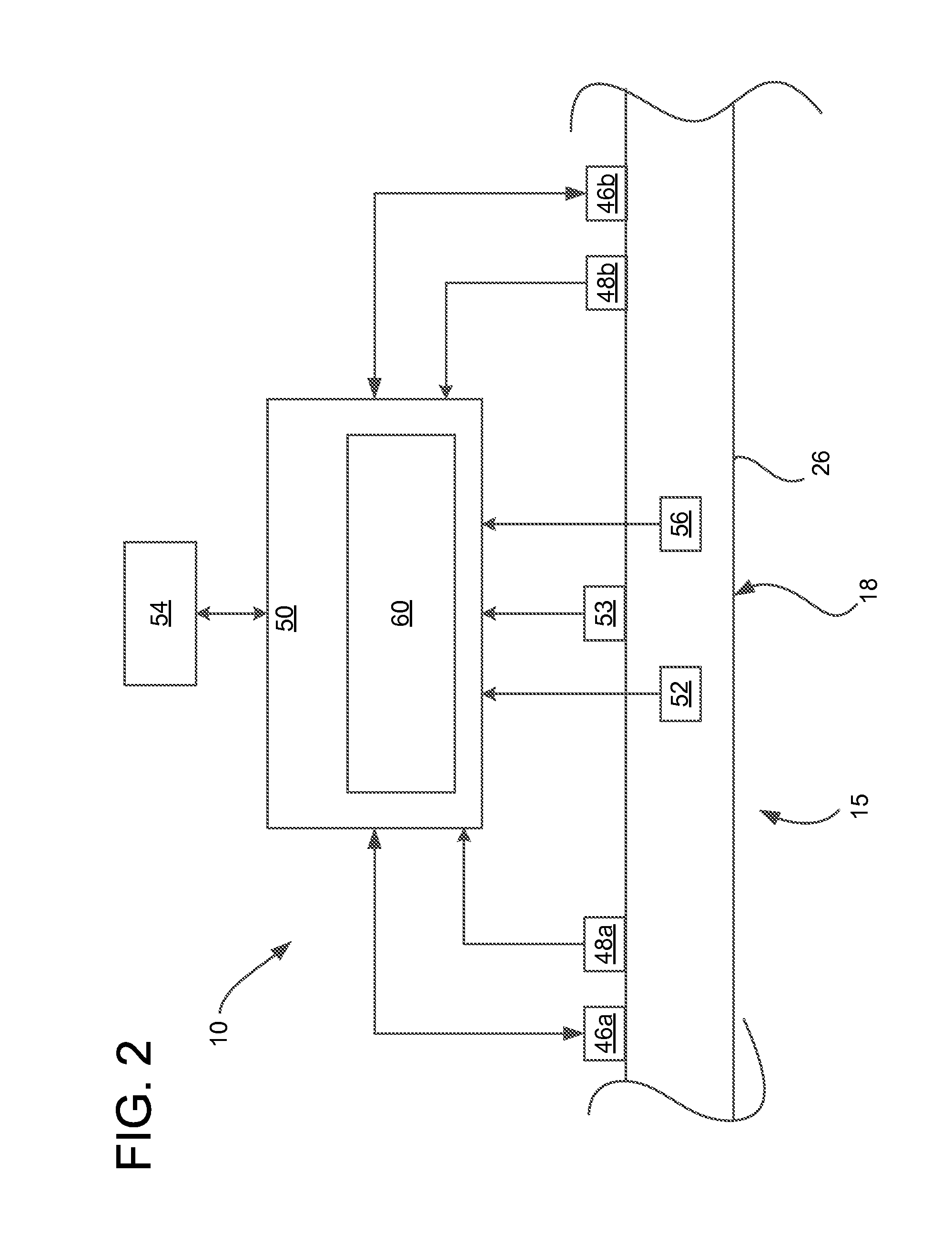
[0024]Referring to FIGS. 1 and 2, an embodiment of a Coriolis flowmeter is generally indicated at reference number 10. In the illustrated embodiment, the flowmeter 10 includes a flowtube 15 comprising a pair of conduits 18, 20. The flowmeter 10 is fluidly connected to a pipeline (not shown) at upstream and downstream flanges 12. Fluid flows into an inlet of the flowmeter 10, through each of the conduits 18, 20 (in series), and out an outlet of the flowmeter. Each of the conduits 18, 20 in FIG. 1 has a straight section 26 that is arranged in the same plane with the straight section of the other conduit. The conduits 18, 20 also having a looping configuration. Other configurations of the conduits (e.g., straight tube configurations, U-shaped configurations, etc.) are also possible.

[0025]The flowmeter 10 has a pair of drivers 46a, 46b, positioned to drive oscillations of the flowtube 15, as illustrated in FIG. 1, but it is possible to drive oscillation of a flowtube using only a single...


PUM


Abstract

A system for evaluating a flow rate measurement includes a flowmeter and a diagnostic system. The diagnostic system is configured to perform a diagnostic test for detecting a physical change in the flowmeter that could impair operation of the flowmeter, output a result of the diagnostic test, evaluate a reliability of the diagnostic test using information about a process condition, and output an indication of the reliability of the diagnostic test.

Description

FIELD OF THE INVENTION[0001]The present invention relates to flowmeters, and more particularly to systems and methods for meter verification of a flowmeter.BACKGROUND OF THE INVENTION[0002]Various flowmeters are used to measure the flow rate of a fluid through the meter. Some examples include vortex flowmeters, magnetic flowmeters, Coriolis flowmeters, and others.[0003]A Coriolis flowmeter is one type of flowmeter that is used to measure mass flow rate and density of a fluid. In a conventional Coriolis flowmeter, fluid flows through one or more conduits (broadly, a flowtube) as one or more drivers oscillates the conduits. Two or more sensors detect the motion of the flowtube at different locations along the flowtube. Forces associated with acceleration of fluid flowing through the oscillating flowtube produce a phase difference in the signals from the sensor. This phase difference is related to the mass flow rate of fluid through the flowtube. Thus, a measurement of mass flow rate c...

Claims


Application Information

Patent Timeline
IPC IPC(8): G01F25/00G01F1/32G01F1/58G01F1/84
CPCG01F25/0007G01F1/58G01F1/32G01F1/845G01F1/8413G01F1/8486G01F15/10G01F25/00G01F1/74G01F1/8436G01F15/024G01F25/10
Inventor PLAZIAK, MICHAEL T.MATTAR, WADE
Owner SCHNEIDER ELECTRIC SYST USA INC
Why Eureka
Try Eureka