Methods for managing flow control valves in process systems

a technology of flow control valves and process systems, applied in the direction of ratio control, testing/monitoring control systems, instruments, etc., can solve the problems of affecting the process variable, the edge of the gate can be worn-away by abrasives, and the particular process variable is not easily measured, so as to achieve the effect of reducing the amount of signal definition, reducing the accuracy of overall process control, and reducing the efficiency of overall process control

Inactive Publication Date: 2008-07-31
HALLIBURTON ENERGY SERVICES INC
View PDF8 Cites 28 Cited by
  • Summary
  • Abstract
  • Description
  • Claims
  • Application Information

AI Technical Summary

Benefits of technology

[0013]In FIG. 6, one effect of dead band on process control is illustrated. FIG. 6 shows changes in control signal where a valve has a dead band as shown in 620. Four small steps of change in control signal 600 are made from Time=0 to Time=A, before the dead band is exceeded on the fifth step, finally resulting in a change in valve displacement 610 (and the concomitant change in material flow rate). The pattern is repeated to Time=B and Time=C. However, the process controller then begins to send only 3 steps of change. For the first three steps from Time C, the valve shaft is displaced. But upon reversal of direction in signal, no displacement occurs, through to Time=D, because the dead band is not exceeded. The process controller is calling for changes in the process variable of flow, but because the dead band is so great in relation to the finer calls of control, the calls are never acted on. The net result is precision and responsiveness in overall process control is lost. Further, as wear or adjustments occur over time, the dead band increases, and process control gets increasingly less effective.
[0014]As a further source of error in digital signal control systems, FIG. 7 shows the error effect of quantization as analog signals are converted to digital signals (“A / D” conversion). For example, the signaled flow rate from a flow meter can be a 5 to 20 milliamp analog electrical signal 700, which is a continuous range of values. After quantization, the signal is now represented by a relatively small set of discrete symbols or integer values shown as digitized signal 710. Quantization can introduce error into signal processing because signal definition is lost between the different digital intervals, as shown in 720. Thus, as the true analog signal increase from 720A to just under 720B, the converted digital signal value remains the same. This amount of signal definition is thus lost. Because most modern control systems utilize A / D converters, further error is thus often introduced into control algorithms.
[0015]Because of the wear over time of mechanical actuator-to-valve linkages and flow-regulating elements of control valves, there is a need for accurate determination, compensation, and management of the effects of such wear in real time during process operations. More particularly, there is a need to reduce the uncertainty associated with hydrocarbon production operations.

Problems solved by technology

Additionally, interaction with other loops in the process network can cause disturbances that can affect the process variable.
Sometimes, a particular process variable is not easily measured.
Such linkages, being mechanical devices, are subject to wear over time, resulting in many cases, as looseness, or mechanical slack.
For example, in a gate valve, the edge of the gate can be worn-away by the abrasive action of fluids or solids.
Wear over time can cause Cv to change.
The net result is precision and responsiveness in overall process control is lost.
Further, as wear or adjustments occur over time, the dead band increases, and process control gets increasingly less effective.
Quantization can introduce error into signal processing because signal definition is lost between the different digital intervals, as shown in 720.
Because most modern control systems utilize A / D converters, further error is thus often introduced into control algorithms.

Method used


Image

  • Methods for managing flow control valves in process systems
  • Methods for managing flow control valves in process systems
  • Methods for managing flow control valves in process systems

Examples


example 1

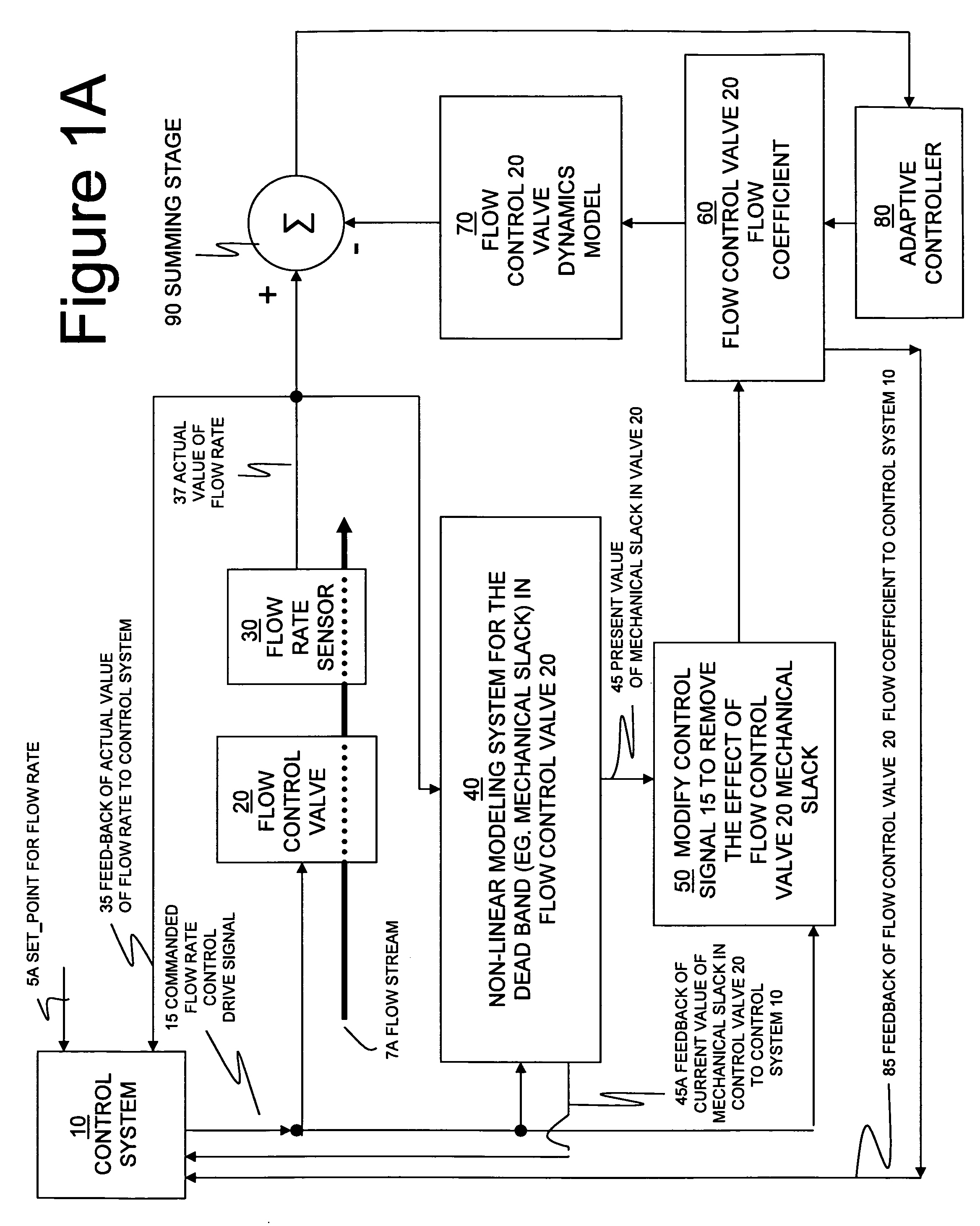
[0052]At a hydrocarbon production site, a process fluid flow stream was passed through a rotary-actuated control valve and a flow meter for a period of about 4300 seconds at flow rates varying between 150 and 300 gallons per minute. FIG. 8 shows the recorded (e.g. “measured”) data for the actual flow rate as measured by the actual flow meter, represented in FIG. 1A as flow rate sensor 30, and as regulated by the actual rotary control valve (flow control valve 20), which was being signaled by an automatic controller (within control system 10). FIG. 8 also shows a simulated (e.g. “estimated”) flow rate using the systems and methods of the present innovations. Note that the drive signal (signal 15) data to the rotary control valve was also recorded, but is not displayed in FIG. 8.

[0053]Using the method of FIG. 1A, both measured flow rate (signal 37) data and the drive signal data were processed at a later time off-line in a control algorithm simulation program, “MATLAB”, from The MathW...


PUM


Abstract

Methods for managing the operational condition of flow control valves in process systems. As a control valve experiences mechanical wear during operation, the physical changes to the valve can alter its dead band and flow coefficient. A non-linear dynamic model determines the present dead band by modeling the relationship between the actual flow through the valve and the commanded drive signal to the valve. The present valve flow coefficient can be determined by removing the dead band from the drive signal and using that modified signal in a flow rate model for the valve to adaptively find the flow coefficient value which matches the predicted flow from the flow rate model to the present measured flow from a flow rate sensor. The present dead band and flow coefficient can be used to update valve control algorithms and to make valve maintenance decisions.

Description

BACKGROUND AND SUMMARY OF THE INVENTION[0001]The following applications filed concurrently herewith are not necessarily related to the present application, but are incorporated by reference herein in their entirety: “Methods to Monitor Sensor and Actuator Health and Performance” (U.S. patent application Ser. No. ______, filed simultaneously with the effective filing date of the present application, Attorney Docket Number HES-2005-IP-019666U1); “Systems for Monitoring Sensor and Actuator Health and Performance” (U.S. patent application Ser. No. ______, filed simultaneously with the effective filing date of the present application, Attorney Docket Number HES-2005-IP-019666U2); and “Systems for Managing Flow Control Valves in Process Systems” (U.S. patent application Ser. No. ______, filed simultaneously with the effective filing date of the present application, Attorney Docket Number HES-2005-IP-019666U4).[0002]Process plants, such as those located at a modern hydrocarbon production s...

Claims


Application Information

Patent Timeline
Patent Type & Authority Applications(United States)
IPC IPC(8): G05D7/00
CPCG05B13/041G05B23/0283G05D7/0635
Inventor DYKSTRA, JASON D.
Owner HALLIBURTON ENERGY SERVICES INC
Why Eureka
Try Eureka