Pressure sensor

Active Publication Date: 2016-05-05
HL MANDO CORP
View PDF1 Cites 10 Cited by
  • Summary
  • Abstract
  • Description
  • Claims
  • Application Information

AI Technical Summary

Benefits of technology

The present invention provides a pressure sensor that can improve assembly efficiency by aligning each part during assembly. This results in a more reliable and accurate pressure sensor that is simple to assemble.

Problems solved by technology

When a driver steps on a brake pedal to generate a braking force, if a braking pressure is larger than road conditions or a friction force at the wheel brake generated by the braking pressure is larger than the braking force generated from tires or a road surface, a slip phenomenon that the tires slide on the road surface may occur in the brake system.
As described above, the existing pressure sensor suffers from the soldering process to electrically connect between the first printed circuit board and the second printed circuit board.
Therefore, the pressure sensor needs the supporter supporting the second printed circuit board in a horizontal state as described above, and therefore the number of parts is increased, thereby making the assembling process complicated.
For this reason, there is a problem in that a shape of the supporter is complicated.

Method used


Image

  • Pressure sensor
  • Pressure sensor
  • Pressure sensor

Examples


Embodiment Construction

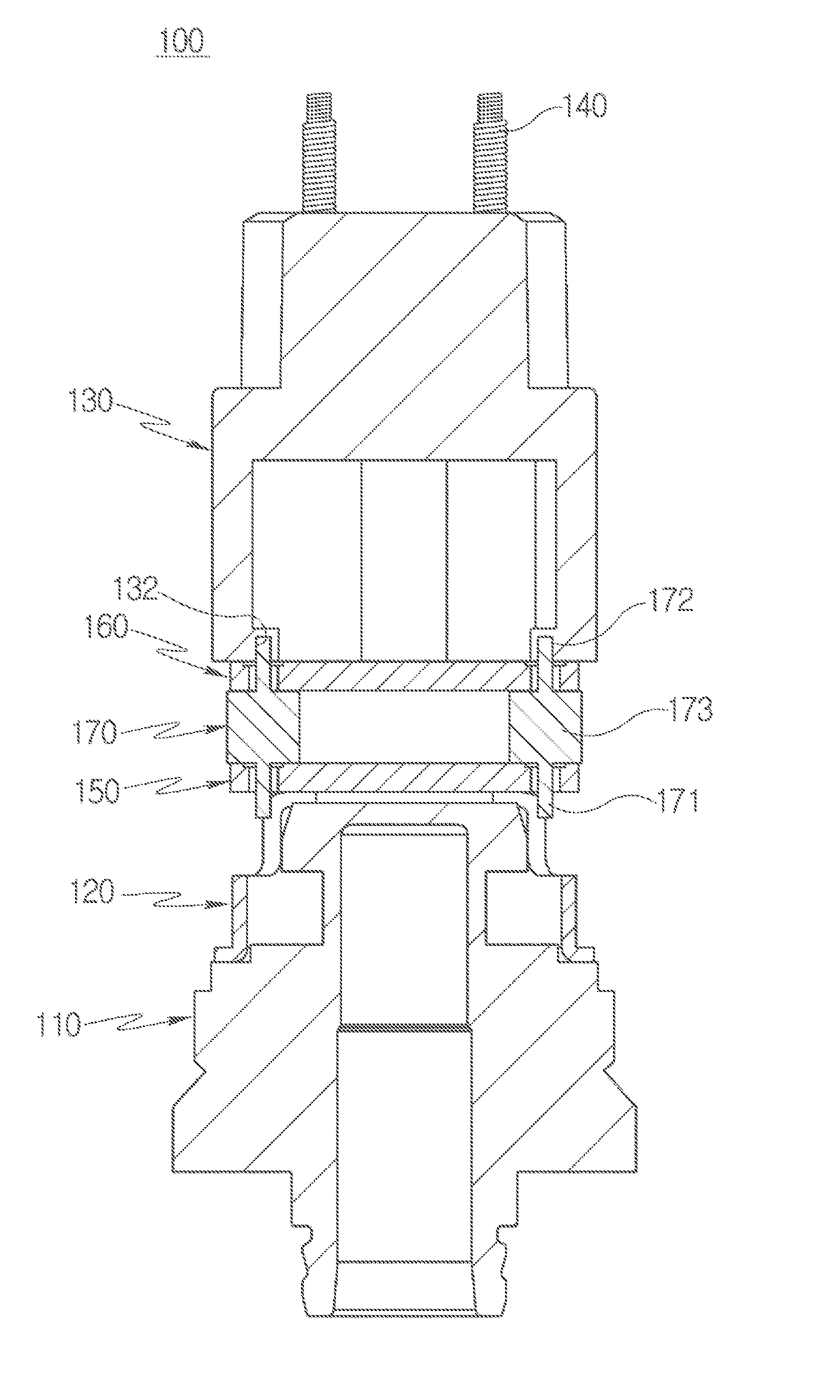
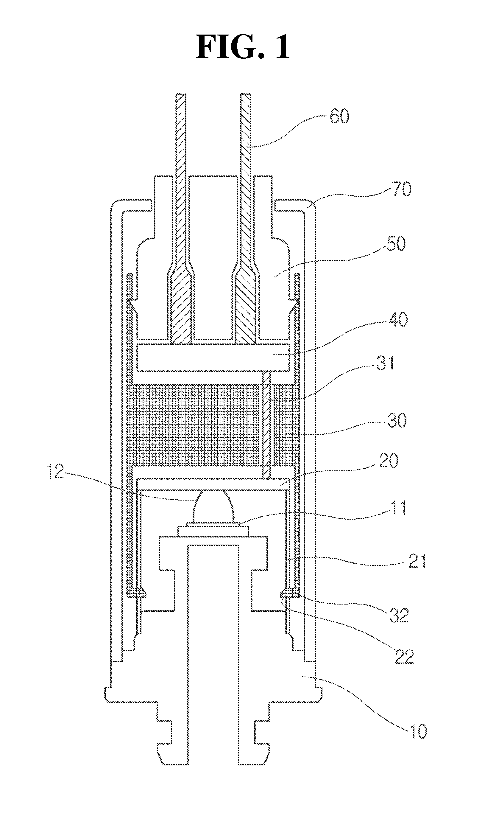
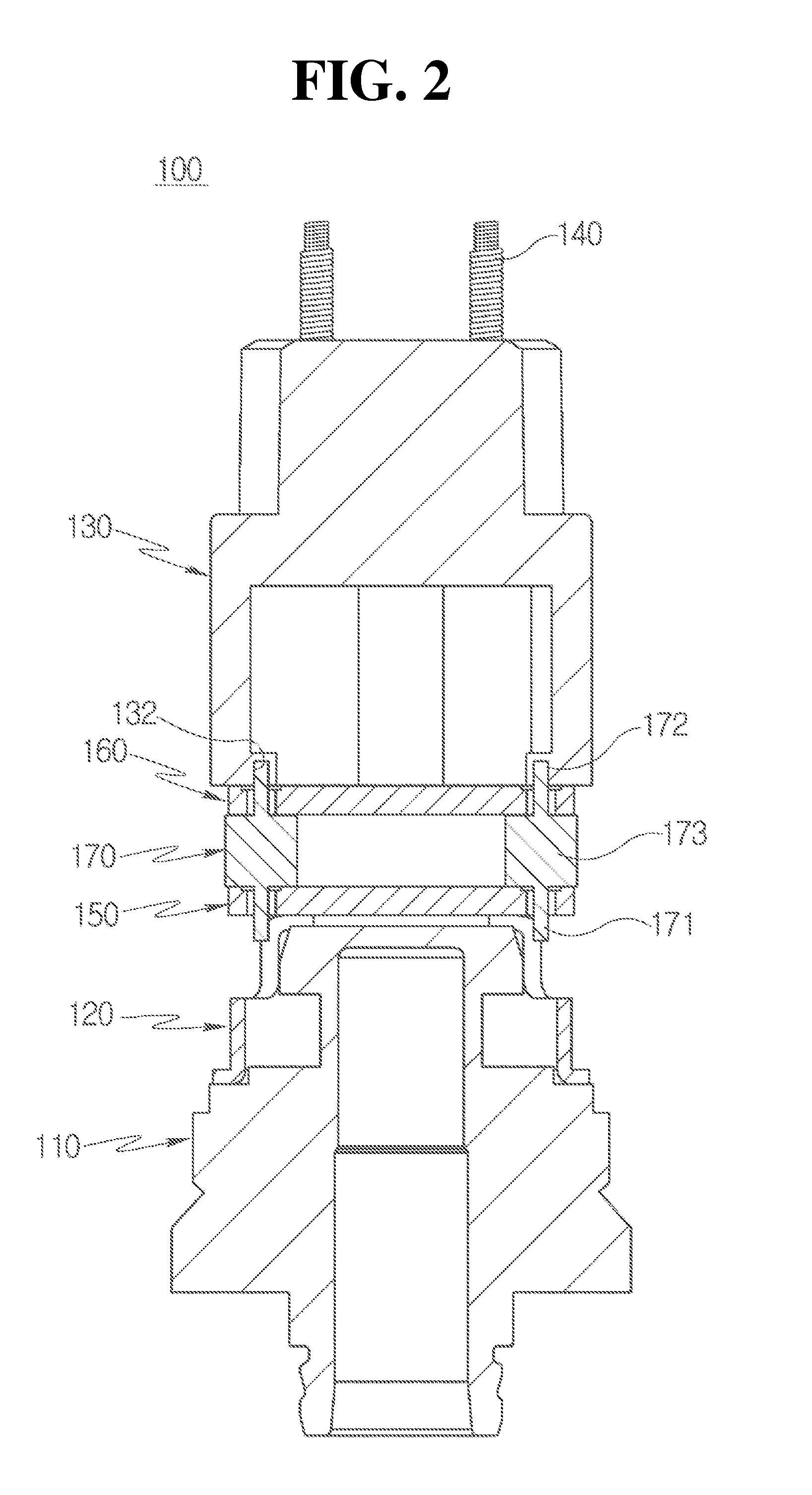
[0061]Hereinafter, a pressure sensor according to an exemplary embodiment of the present invention will be described in detail with reference to the accompanying drawings.

[0062]During the process, a thickness of lines, a size of components, or the like, illustrated in the drawings may be exaggeratedly illustrated for clearness and convenience of explanation. Further, the following terminologies are defined in consideration of the functions in the present invention and may be construed in different ways by intention or practice of users and operators. Therefore, the definitions of terms used in the present description should be construed based on the contents throughout the specification.

[0063]In addition, the following embodiments are not limited to the scope of the present invention but illustrate only the components included in the claims of the present invention and it will be appreciated that embodiments including components which are included in the spirit of the specification ...


PUM


Abstract

Disclosed is to a pressure sensor including: a metal diaphragm configured to have a pressure sensing part disposed thereover; a first support configured to be coupled with the metal diaphragm; a first printed circuit board configured to be disposed over the pressure sensing part while being supported to the first support and electrically connected to the pressure sensing part; a connector configured to have a lower portion press-fitted with the first printed circuit board; a second printed circuit board configured to be electrically connected to the first printed circuit board through the connector while being press-fitted with an upper portion of the connector and supported by the connector; a second support configured to be disposed over the second printed circuit board; and a spring electrode configured to have an upper end protruding upward of the second support and have a lower end connected to the second printed circuit board.

Description

CROSS-REFERENCE TO RELATED APPLICATION[0001]This application claims priority to Korean Patent Application No. 10-2014-0152666, filed on Nov. 5, 2014, the disclosure of which is incorporated herein by reference in its entirety.BACKGROUND OF THE INVENTION[0002]1. Field of the Invention[0003]Exemplary embodiments of the present invention relate to a pressure sensor, and more particularly, to a pressure sensor with improved assembling performance.[0004]2. Description of the Related Art[0005]A pressure sensor is a part which is widely used in automobile, environmental equipment, medical instrument, etc. The pressure sensor has been used under conditions such as generation of vibrations, a sudden change in pressure, measurement of a wide range of use temperature, and high-pressure atmosphere.[0006]A specific use example of the pressure sensor will be described below.[0007]Generally, a brake system for deceleration or braking is provided in a vehicle. The brake system may include a pedal f...

Claims


Application Information

Patent Timeline
IPC IPC(8): G01L9/00
CPCG01L9/0048G01L19/0061G01L9/0002G01L19/147
Inventor LEE, GON JAE
Owner HL MANDO CORP
Why Eureka
Try Eureka