
Method for Extending the Time Between Out-of-Service, In-Tank Inspections Using Ultrasonic Sensor

a technology of ultrasonic sensor and storage tank, which is applied in the direction of instruments, using mechanical means, and fluid detection at leakage points, etc., can solve the problems of difficult estimation, less than optimal maintenance and repair, and high cost of out-of-service inspection, so as to safe prolong the time between out-of-service inspections. , the effect of safe prolonging the time between out-of-service inspections

Inactive Publication Date: 2016-05-05
VISTA RES INC
View PDF6 Cites 6 Cited by
  • Summary
  • Abstract
  • Description
  • Claims
  • Application Information

AI Technical Summary

Benefits of technology

The invention provides a method and apparatus for safely extending the time between inspections of a tank that uses a risk-based approach and the results of a leak detection test and actual measurements of the thickness and corrosion rate of the tank floor. The technical effect is to improve the safety and reliability of extending the time between inspections, which can save time and money and reduce the likelihood of tank failure.

Problems solved by technology

The routine time interval, which has been the practice, can be very costly and may result in less than optimal maintenance and repair.
An out-of-service inspection is very expensive, not only because of the inspection itself, but the loss of the tank for operations during the inspection, repairs, and maintenance activities.
The former is difficult to estimate because of the limited access to the inside of the tank, particularly the floor of the tank, between out-of-service inspections.
Corrosion to the bottom and top of the tank floor can lead to failure and leakage.
However, the necessary data needed to estimate the likelihood of a failure is difficult to obtain.
The main problem is determination of the condition of the tank floor.
This information is difficult to obtain because access to the inside of the tank is limited.
It is very expensive to take a tank out of service and to perform an inspection.
The costs include the cost of the inspection itself and the lost operational benefit of the tank.
This is especially true for small tank facilities where one or more products cannot be serviced.
Unfortunately, most problems occur in the tank floor where visual access is not possible without tanking the tank out of service, removing the product from the tank, and cleaning the tank.
However, they have not specified methods or acceptable approaches.
The difficulty has been to meaningfully assess the condition of the tank and to meaningfully set a safe inspection interval.
This method is expensive to use and requires a high degree of technician skill to obtain accurate results.
Furthermore, AE methods do not measure floor thickness and are not reliable as leak detection methods.
In addition, these methods are not generally accepted in all circles.
The main issue is that AE methods do not measure floor thickness and as a consequence, corrosion rates and floor thickness cannot be accurate evaluated.
However, in general, our assessment of these results concludes that the AE method leads to correct decisions about the condition of the tank floor only 76.7% of the time with a probability of false alarm of 14.5% and a probability of missed detection of 8.8%.
Even the correct decisions are not easy to determine because false alarms and missed detections happens for all grades except A.
First, 64.2% of the tanks tested need little or no maintenance or repair.
Second, 14.2% of the tanks tested need significant maintenance and repair.

Method used


Image

  • Method for Extending the Time Between Out-of-Service, In-Tank Inspections Using Ultrasonic Sensor
  • Method for Extending the Time Between Out-of-Service, In-Tank Inspections Using Ultrasonic Sensor
  • Method for Extending the Time Between Out-of-Service, In-Tank Inspections Using Ultrasonic Sensor

Examples


Embodiment Construction

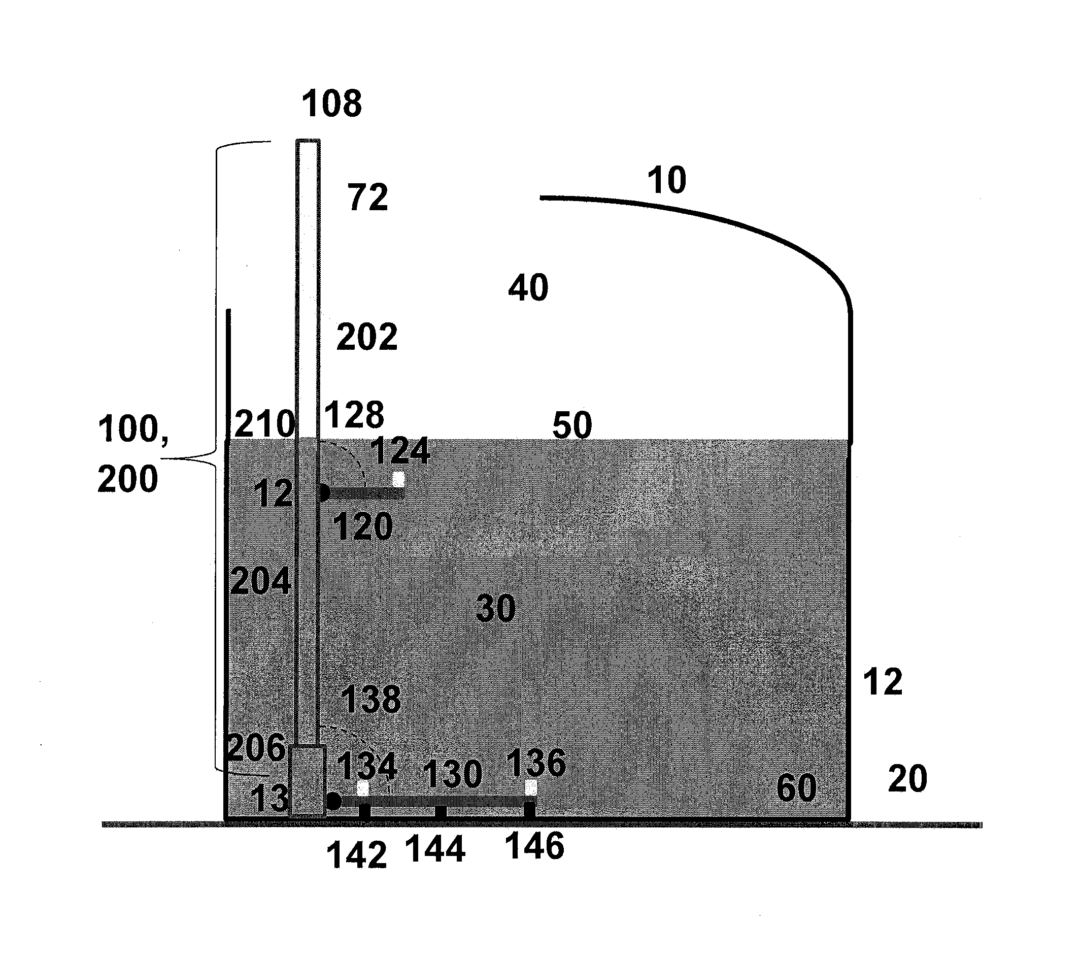
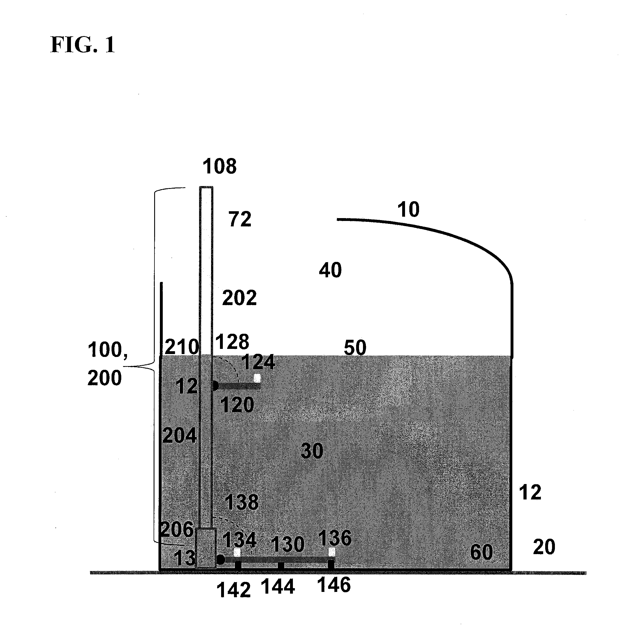
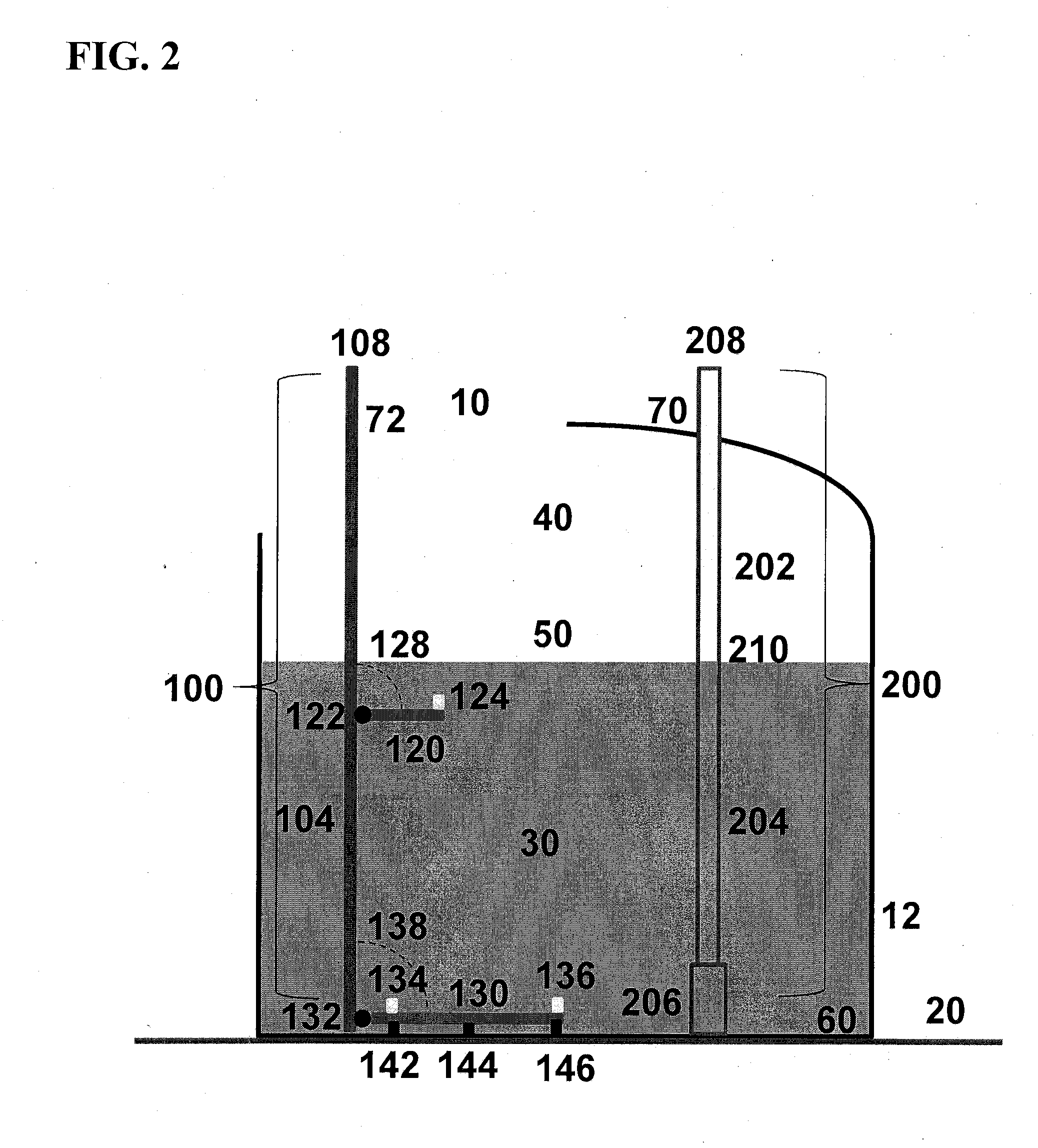
[0053]The method and apparatuses of the present invention can be used to provide critical data and information about the structural integrity of an aboveground or bulk underground storage tank needed to better prioritize and better schedule out-of-service tank inspections for these tanks, because it can be used to assess the condition of the tank floor, i.e., the thickness of the tank floor, the rate of corrosion of the floor, and whether or not any holes or cracks exist in the floor. If the floor is in good condition, then it is possible to postpone a scheduled inspection or to extend the time between inspections so that the maintenance and repair activities can focus on those tanks with the most need.

[0054]The method is comprised of a leak detection test and one or more actual measurements of the thickness and corrosion condition of the bottom floor of the tank in a least one section of the tank. This approach will work well for tanks in which the corrosion is either small or rela...


PUM

PropertyMeasurementUnit
timeaaaaaaaaaa
timeaaaaaaaaaa
diametersaaaaaaaaaa

Abstract

A method and apparatuses to extend the time interval between out-of-service, in-tank inspections while insuring structural integrity using a risk-based, Bayesian statistical approach comprised of a passing leak detection test and the using the results from (1) tank floor thickness measurements, (2) prior out-of-service tank floor inspection results, and / or (3) acoustic emission corrosion maps of the tank floor to estimate the minimum thickness and maximum corrosion rate of the tank during the extension period. The present invention uses an in-tank, mass-based leak detection system to establish tank integrity, three or more ultrasonic (UT) thickness measurement sensors for measurements of the tank floor at one location, and to establish the spatial distribution of corrosion of the tank floor, one or more prior API 653 / 12R1 or STI SP001 tank floor thickness inspections and / or three or more in-tank AE sensors mounted inside the tank with vertical and horizontal locations in an oblique plane relative to the tank floor.

Description

RELATED APPLICATIONS[0001]This application claims priority to U.S. Provisional Patent Application Ser. No. 61 / 634,766 filed Mar. 5, 2012, and which is hereby incorporated by reference.FIELD OF INVENTION[0002]The present invention relates to a method for extending the time between inspections of out-of-service storage tanks for petroleum products and chemicals.BACKGROUND OF THE INVENTION[0003]There are several standards for inspecting the integrity of welded or riveted, atmospheric pressure, aboveground storage tanks (ASTs) after they have been placed in service. API 653 (API 12R1 is similar to API 653 but is designed for production tanks) covers the maintenance inspection, repair, alteration, relocation, and reconstruction of such tanks. It is a performance-based inspection with the time between inspections being 10 years or more for out-of-service inspections and 5 years or less for in-service inspections. The scope of this API publication is limited to the tank foundation, bottom,...

Claims


Application Information

Patent Timeline
Patent Type & Authority Applications(United States)
IPC IPC(8): G01N17/00G01N29/14
CPCG01N29/14G01N17/00G01M3/24G01N2291/02854G01N2291/2695
Inventor MARESCA, JR., JOSEPH W.FORD, STEPHEN D.MANN, DOUGLAS W.
Owner VISTA RES INC
Learn More