

Shock absorber with a bayonet fitting
a technology of shock absorber and bayonet, which is applied in the direction of gear train, instruments, horology, etc., can solve the problems of rigid attachment between elastic return means and timepiece movements, and the type of shock absorber device cannot be used in more compact timepiece movements, so as to achieve less stress and more compact
- Summary
- Abstract
- Description
- Claims
- Application Information
AI Technical Summary
Benefits of technology
Problems solved by technology
Method used
Image

Examples
first embodiment
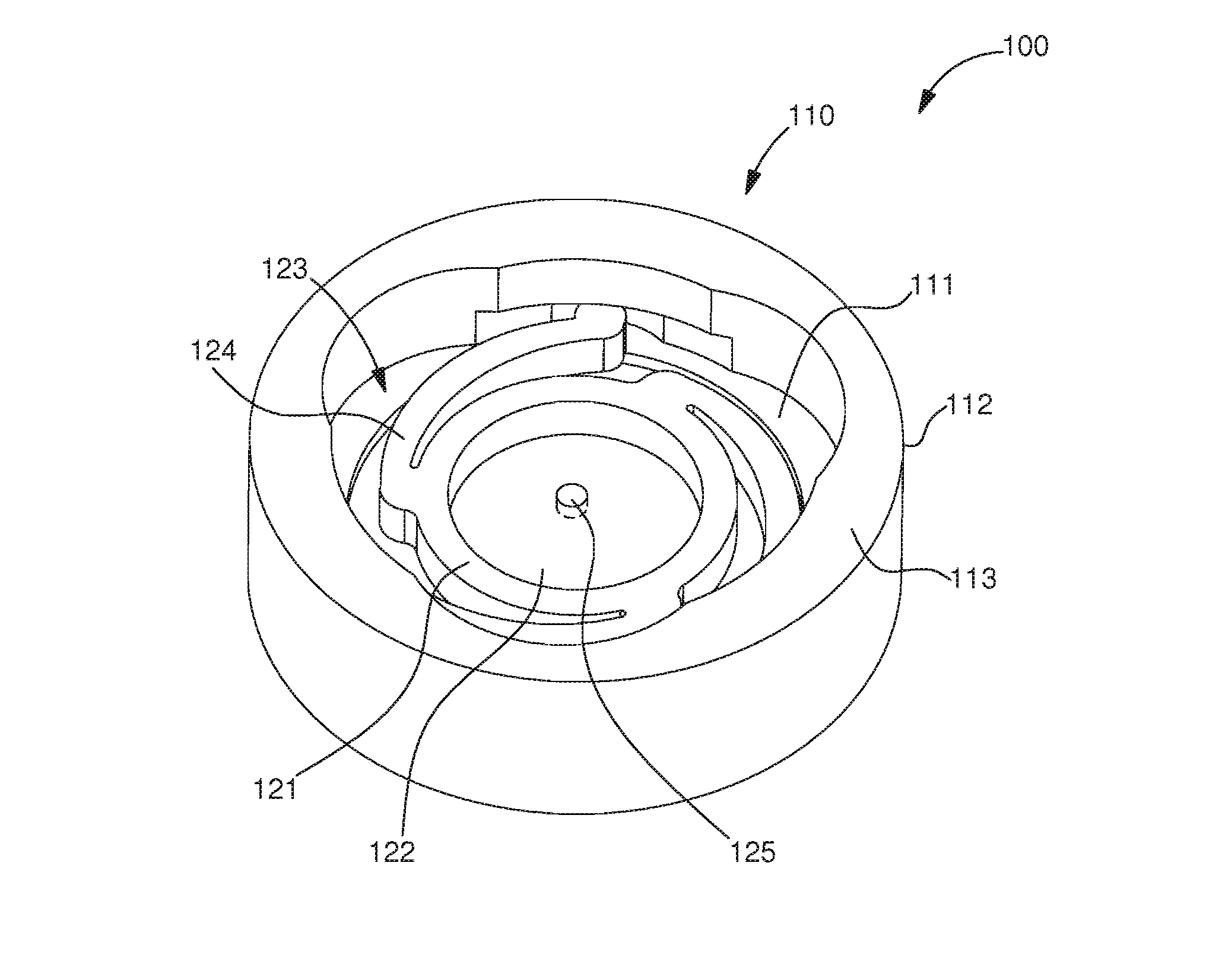
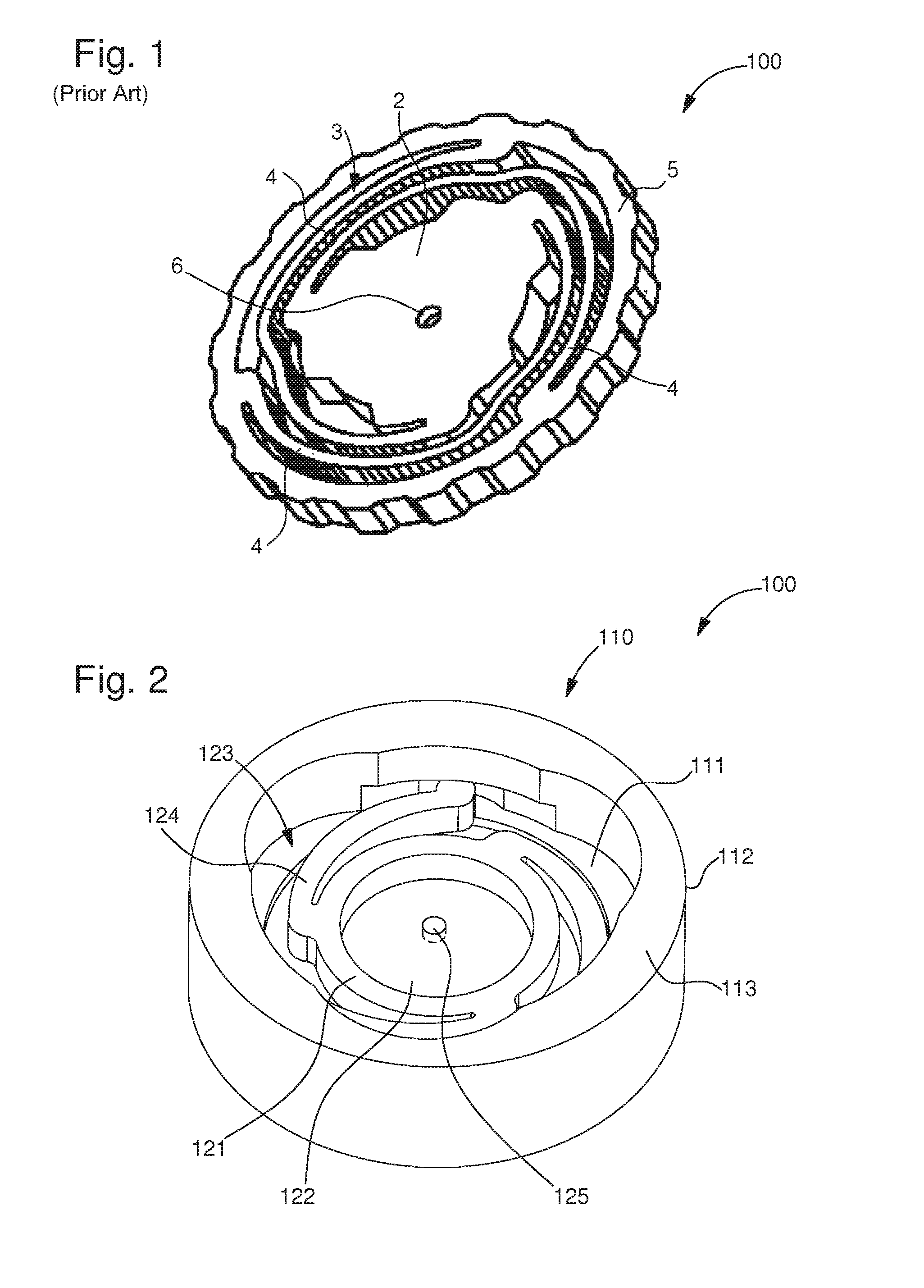
[0032]FIGS. 2 and 3 show a shock absorber device 100 according to the invention. This shock absorber device can be used for a part of a timepiece.
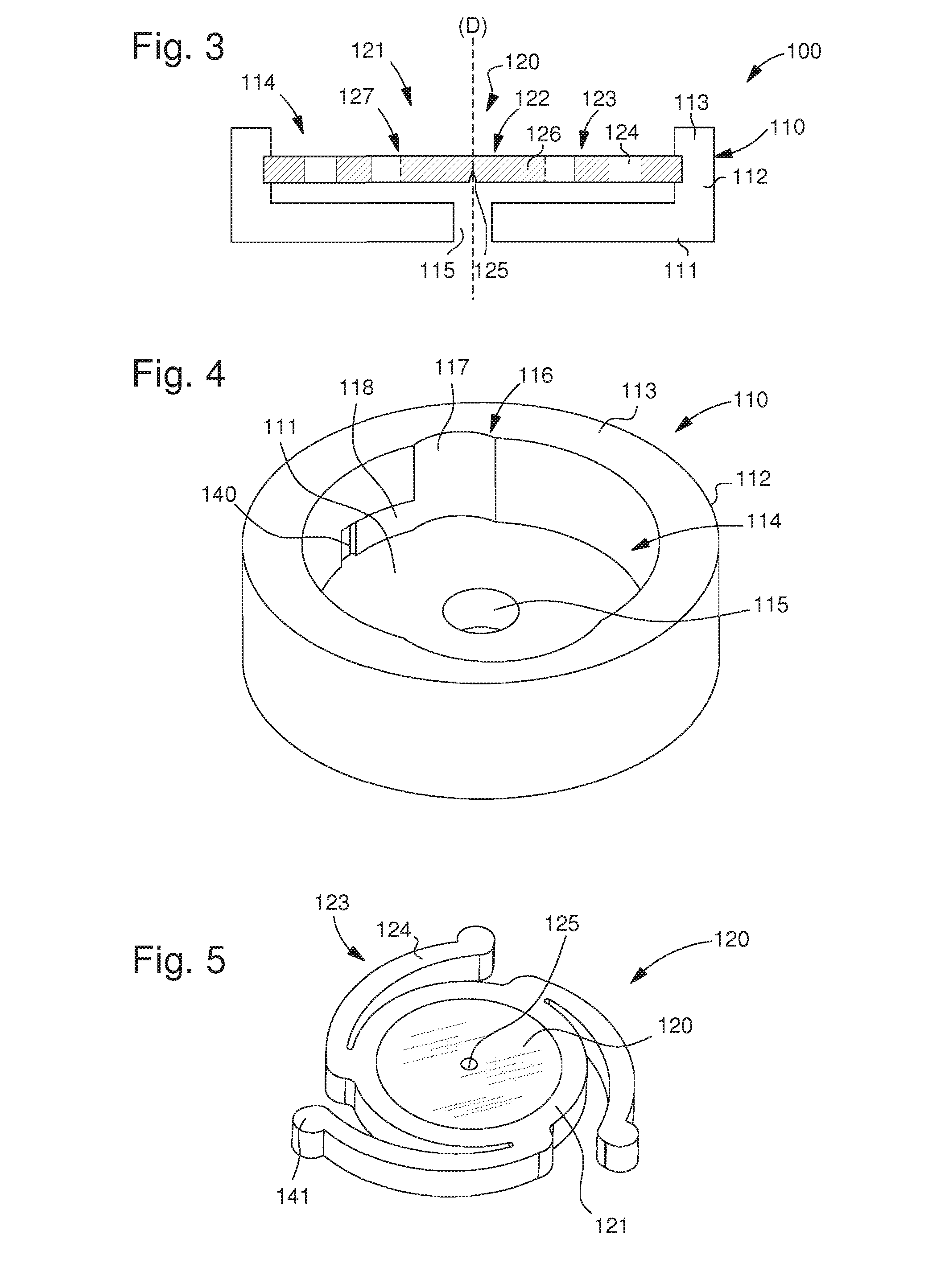
[0033]Shock absorber or shock resistant device 100 includes a hollow support 110 including a base cup 111 surmounted by a peripheral rim 112 which is delimited, opposite said cup, by an upper surface 113. The cup and the rim together define a housing 114 seen in FIGS. 3 and 4.
[0034]Support 110 may either be an independent part that is pressed in or attached by any other known means to the frame of the timepiece movement, or form part of another component of the movement, such as a bridge or a plate.
[0035]A pivot system 120 extending along an arbor D is placed inside housing 114, defined by cup 111 and rim 112. This pivot system 120 includes a circular base 121 in the form of a disc. This base 121 may be made of a metal or single crystal type material, such as silicon or a polycrystalline type material such as ceramic or ruby or sapphire.
[0...
second embodiment
[0050]In a second embodiment, circular base 121 has a central orifice 121a (not shown) in which a pivot element 122 is accommodated. This configuration allows circular base 121 and elastic return means 123 to be made of a first material and pivot element 122 of a second material. The first and second materials can thus be selected according to requirements. For example, a material having elastic properties will be preferred for arms 124, while a hard material having some friction and wear resistant properties will be preferred for pivot element 122.
[0051]In a first example embodiment seen in FIGS. 5 and 6, pivot element 122 takes the form of a single jewel 127, for example made of ruby. This single jewel 127 is placed in orifice 121a of circular base 121 and is provided with a blind or through hole in which the arbor shank engages. The diameter of the hole is calculated such that the shank engaged therein can turn freely with a minimum clearance. The single jewel 127 is secured in o...
third embodiment
[0057]In a third embodiment visible in FIG. 10, it can be provided that the shock absorber device 100 includes two pivot systems 120. These pivot systems are advantageously mounted in housing 114 on support 110 by a bayonet fitting system. To achieve this, several possibilities may be envisaged.
[0058]A first possibility consists in using the same cavity 116 for both pivot systems 120. This cavity 116 is thus formed by a recess 117, which is parallel to said arbor D and open on upper surface 113, and two blind grooves 118, which are secant with said first recess and opposite upper surface 113. These two grooves 118 are parallel and each is used for locking one curved arm 124 of one pivot system in a bayonet fitting. The space between the two pivot systems 120 is thus defined by the space between the two grooves 118.
[0059]A second possibility consists in having two separate cavities 116, one for each pivot system 120. Each cavity 116 is formed by a recess 117, which is parallel to sai...
PUM
 Abstract
Description
Claims
Application Information