Time synchronization in a communications network with a plurality of network nodes

Active Publication Date: 2016-05-05
SIEMENS AG
View PDF4 Cites 6 Cited by
  • Summary
  • Abstract
  • Description
  • Claims
  • Application Information

AI Technical Summary

Benefits of technology

The patent describes a method to prevent synchronization faults in a communications network. The method avoids the transfer of global synchronization faults into subnetworks, while still maintaining local synchronization. If there are individual network nodes without associated subnetworks, they act as global master nodes. The method also allows for the detection and removal of faulty network nodes from the communications network. The technical effect of this invention is to prevent fault propagation and improve the overall reliability and efficiency of the communications network.

Problems solved by technology

Conventional methods for time synchronization have the disadvantage that, in the case of a fault in the master node, the synchronization becomes faulty in all slave nodes, which leads to a fault propagation with regard to the timing characteristic in the entire communications network.
As a consequence, synchronism may no longer be guaranteed for all parts of the network.

Method used


Image

  • Time synchronization in a communications network with a plurality of network nodes

Examples


Embodiment Construction

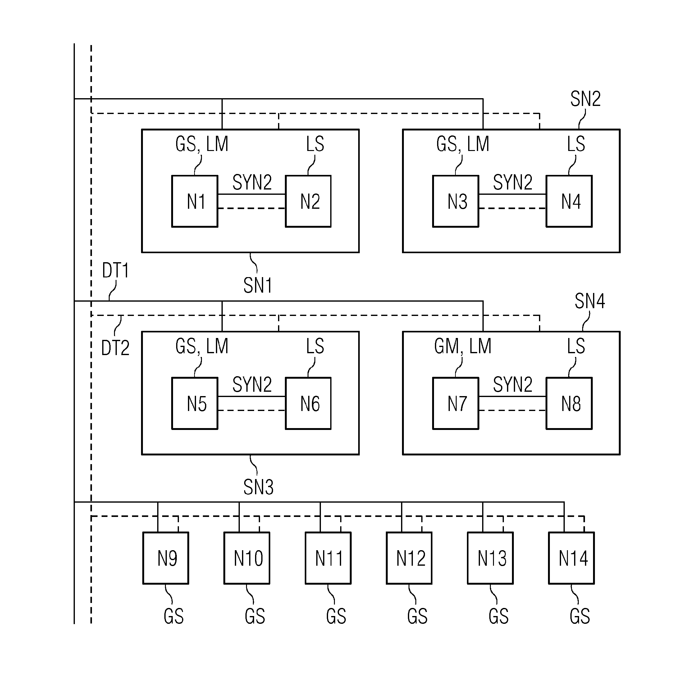
[0023]The communications network shown in FIG. 1 includes a plurality of network nodes N1, N2, N3, . . . , N14. In this context, the communications network may be used in any technical applications. For one use, the individual network nodes represent the components of a flight control or drive control system in an aircraft or vehicle respectively (e.g., rail vehicle or motor vehicle). The network nodes N1 to N8 may be, for example, central control computers in the system, whereas the network nodes N9 to N14 represent, for example, sensors or actuators. In the communications network of FIG. 1, the individual network nodes may communicate with one another via logical data transport channels. A data transport channel DT1 is indicated, for example, by solid lines, and a further data transport channel DT2 is indicated by dashed lines. The communications network includes four subnetworks SN1, SN2, SN3 and SN4. Each of the four subnetworks SN1, SN2, SN3 and SN4 includes two network nodes N...


PUM


Abstract

One or a plurality of sub-networks are defined in the communications network. Each of the sub-networks includes a plurality of network nodes from the communications network. One or a plurality of the sub-networks represent pre-determined sub-networks, in which respective pre-determined network nodes have both the function of a global slave node and the function of a local master node. The one or the other network nodes of the respective pre-determined sub-networks are local slave nodes. In addition to global synchronization using the global master node and the global slave nodes, local synchronization is also performed in the pre-determined sub-networks using the local master node and the local slave nodes. Thus, in the event of an error outside a pre-determined sub-network, the local synchronization may be continued, whereas the global synchronization is aborted. It is thus avoided that an erroneous synchronization is propagated into corresponding sub-networks.

Description

CROSS-REFERENCE TO RELATED APPLICATIONS[0001]The present patent document is a §371 nationalization of PCT Application Serial Number PCT / EP2014 / 060699, filed May 23, 2014, designating the United States, which is hereby incorporated by reference, and this patent document also claims the benefit of DE201310210775, filed on Jun. 10, 2013, which is also hereby incorporated by reference.TECHNICAL FIELD[0002]The present embodiments relate to time synchronization in a communications network with a plurality of network nodes.BACKGROUND[0003]In communications networks having a plurality of network nodes, the processes performed by the network nodes may be adapted to one another. For this purpose, methods for time synchronization in which clocks contained in the network nodes are synchronized to the clock of a master node are used. One example of a method for time synchronization is the Precision Time Protocol, which is defined in the IEEE 1588 and IEEE 1588v2 standard, respectively. In this p...

Claims


Application Information

Patent Timeline
IPC IPC(8): G06F1/10
CPCG06F1/10H04J3/0638H04J3/0673H04J3/14H04J3/0667
InventorARMBRUSTER, MICHAELBUHL, MICHAEL BERNHARDOBRADOVIC, DRAGAN
OwnerSIEMENS AG