

Semiconductor device
- Summary
- Abstract
- Description
- Claims
- Application Information
AI Technical Summary
Benefits of technology
Problems solved by technology
Method used
Image

Examples
embodiment 1
[0057]In this embodiment, a device of one embodiment of the present invention will be described. In the case where a semiconductor element such as a transistor is used for the device of one embodiment of the present invention, the device of one embodiment of the present invention may be referred to as a semiconductor device.
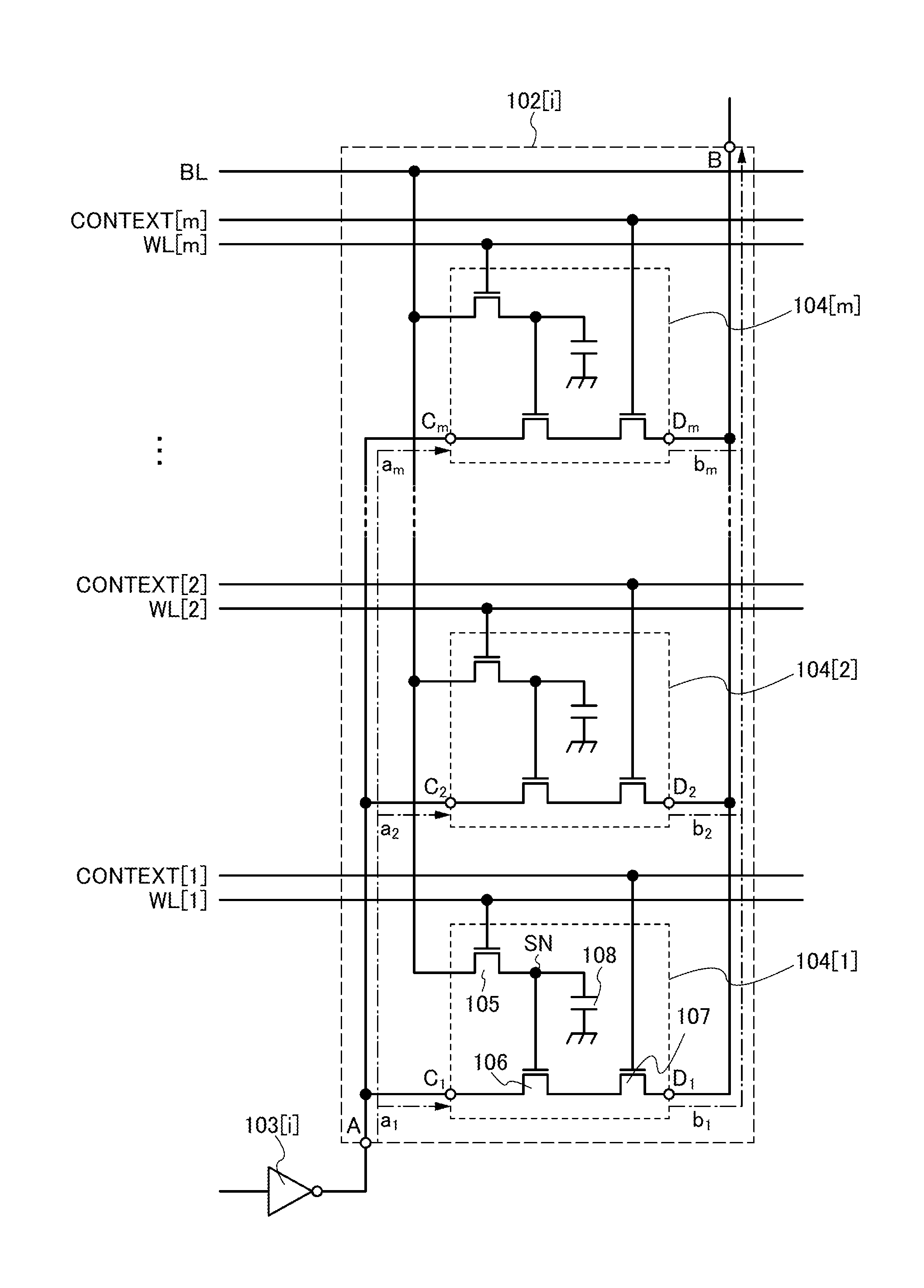
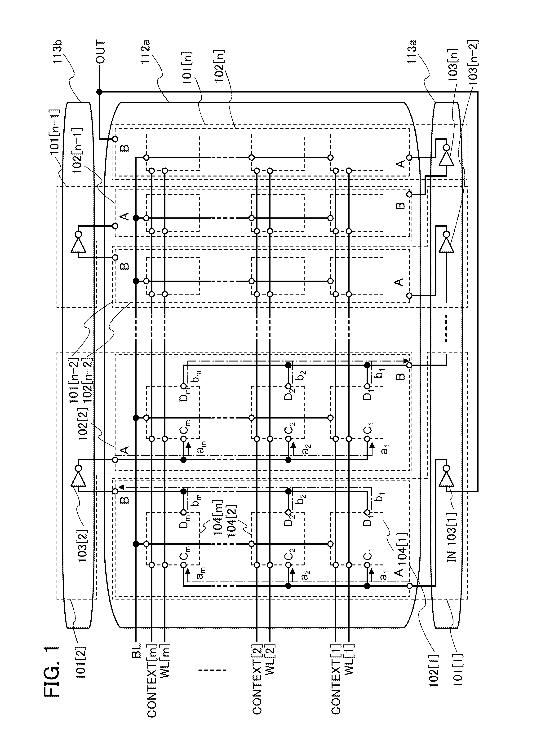
[0058]FIG. 1 illustrates an example of a configuration of a semiconductor device of one embodiment of the present invention. The device in FIG. 1 has a function of generating an alternating current signal such as a clock signal by oscillating and may be referred to as an oscillator (or an oscillator circuit). Specifically, the device in FIG. 1 has a function of changing the frequency (or oscillation frequency) of a signal in accordance with an input voltage and may be referred to as a voltage-controlled oscillator (or a voltage-controlled oscillator circuit).
[0059]The device in FIG. 1 includes circuits 101[1] to 101[n] (n is an odd number of 3 or more). The circu...
embodiment 2
[0159]In this embodiment, a PLL in which the device described in Embodiment 1 is used will be described.
[0160]A PLL illustrated in FIG. 8 includes a phase comparator 201, a loop filter 202, a voltage-controlled oscillator 203, and a frequency divider 204.
[0161]The phase comparator 201 has a function of detecting a phase difference between two input signals and outputting a detection result as a voltage signal. That is, the phase comparator 201 has a function of outputting a phase difference between a signal with a frequency fin and a signal with a frequency fout / N as a voltage signal.
[0162]The loop filter 202 has a function of generating a direct-current voltage signal DATA which is to be input to the voltage-controlled oscillator 203. In addition, the loop filter 202 has a function of removing a high-frequency component from an output signal of the phase comparator 201. An example of the loop filter 202 is a low-pass filter.
[0163]The voltage-controlled oscillator 203 has a function...
embodiment 3
EXAMPLES OF PLAN STRUCTURE AND CROSS-SECTIONAL STRUCTURE OF SEMICONDUCTOR DEVICE
[0167]In this embodiment, examples of the structure of the semiconductor device described in the above embodiment will be described with reference to FIGS. 9A and 9B, FIG. 10, FIGS. 11A to 11C, FIGS. 12A to 12C, FIG. 13 and FIG. 14.
[0168]Note that the following structures are just examples for the semiconductor device described in the above embodiment; the specific structure of the semiconductor device, such as a material or a configuration, is not necessarily limited to that described here.
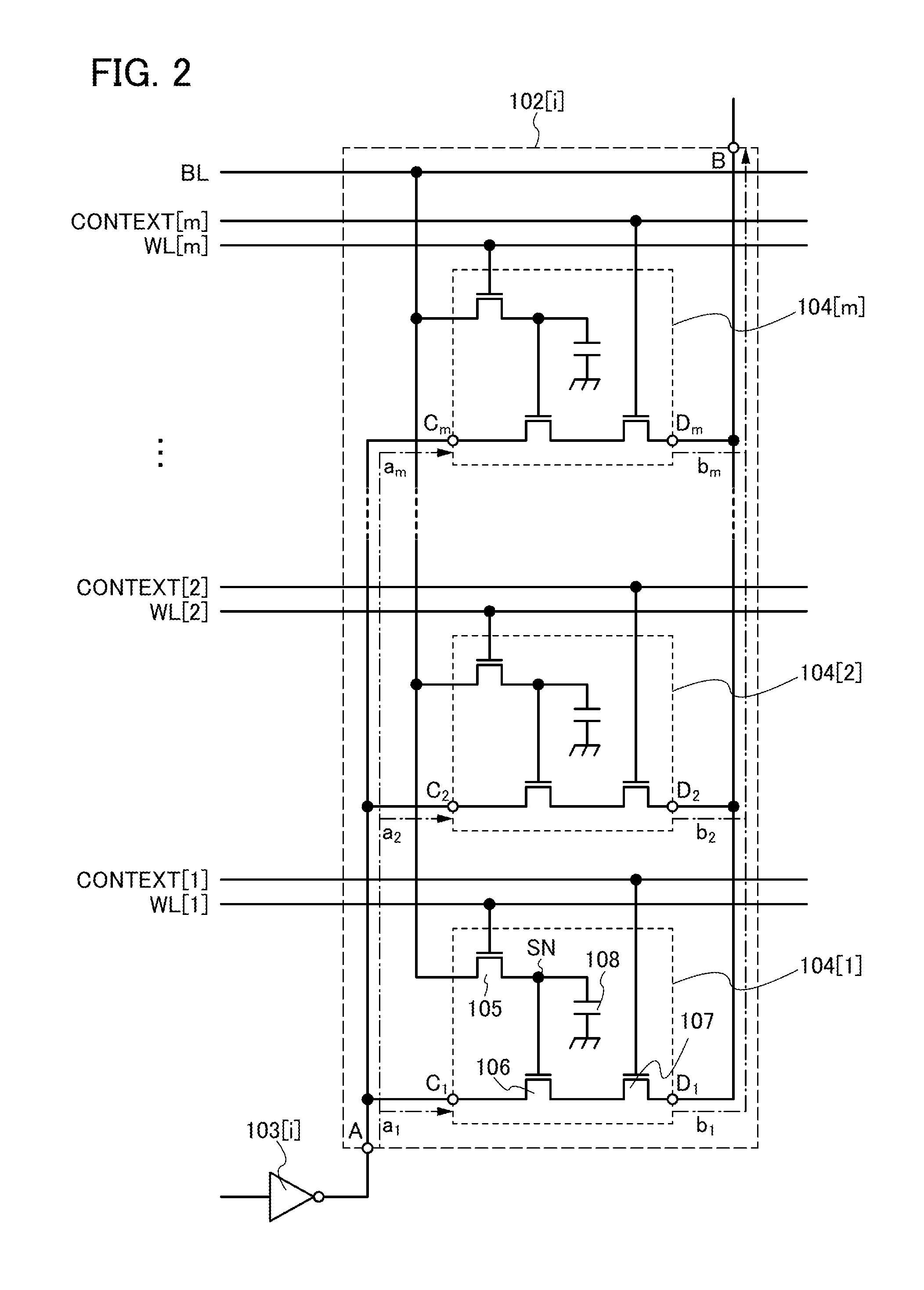
[0169]Examples of the structure of the circuits 104[1] and 104[2] described in the above embodiment with reference to FIG. 1 and FIG. 2 will be described with reference to FIGS. 9A and 9B and FIG. 10, which show the case of m=2. FIGS. 9A and 9B are plan views of the circuits 104[1] and 104[2]. FIG. 10 is a cross-sectional view along the dashed-dotted line X1-X2 and the dashed-dotted line X3-X4 in FIGS. 9A and 9B.
[0170...
PUM
 Abstract
Description
Claims
Application Information