Speaker diaphragm supporting structure

a technology of supporting structure and speaker, which is applied in the direction of transducer details, electrical transducers, electrical apparatus, etc., can solve the problems of inability to effectively lower the lowest resonant frequency of the size-reduced speaker, inferior sound effect, and inconvenient mounting in the new-generation a/v product, so as to reduce the overall height and volume, increase structural strength, and reduce the position of gluing

Inactive Publication Date: 2016-05-05
MEILOON INDAL
View PDF12 Cites 23 Cited by
  • Summary
  • Abstract
  • Description
  • Claims
  • Application Information

AI Technical Summary

Benefits of technology

[0008]A speaker using the diaphragm supporting structure of the present invention can have effectively reduced overall height and volume, and the diaphragm with the supporting legs integrally formed thereon has increased structural strength with reduced gluing positions, which enables accurate alignment of speaker components with one another, simplified assembling procedures and accordingly convenient assembling of the speaker to largely increase the rate of yield of the speaker, and the produced speaker can work normally to output good sound quality without becoming failed easily.

Problems solved by technology

While the conventional speaker with the above structure provides good sound quality, it has a relatively big volume in a fully assembled state and is therefore not suitable for mounting in the new-generation A / V products that have small volume and very limited internal space.
In the event the conventional speaker is correspondingly reduced in size to match the small internal space of the new-generation A / V products, the sound wave output by the size-reduced speaker would not be able to effectively lower its lowest resonant frequency, which disadvantageously results in inferior sound effect.
This is the main cause that prevents the conventional speaker from having an effectively reduced volume.
It is relatively difficult to accurately align the diaphragm and the lower suspension member with the upper and the lower end of the tubular stabilizer, respectively, and complicated procedures are involved in assembling the speaker.
As a result, the speaker would not be able to work normally and would output sound with noise.

Method used


Image

  • Speaker diaphragm supporting structure
  • Speaker diaphragm supporting structure
  • Speaker diaphragm supporting structure

Examples


Embodiment Construction

[0015]The present invention will now be described with a preferred embodiment thereof and by referring to the accompanying drawings.

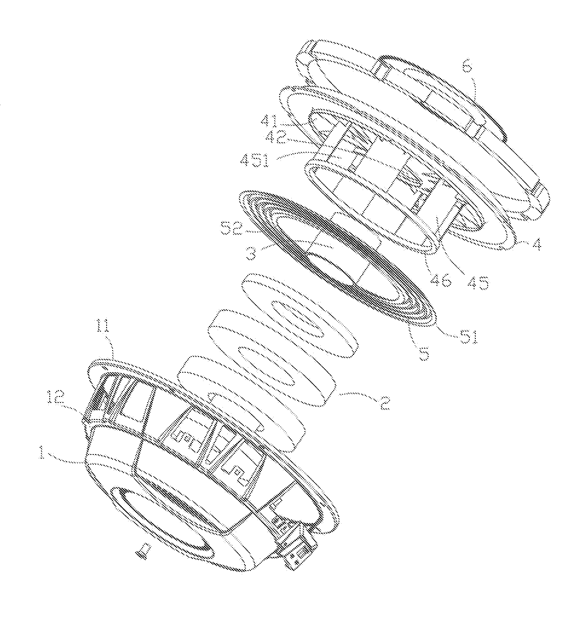
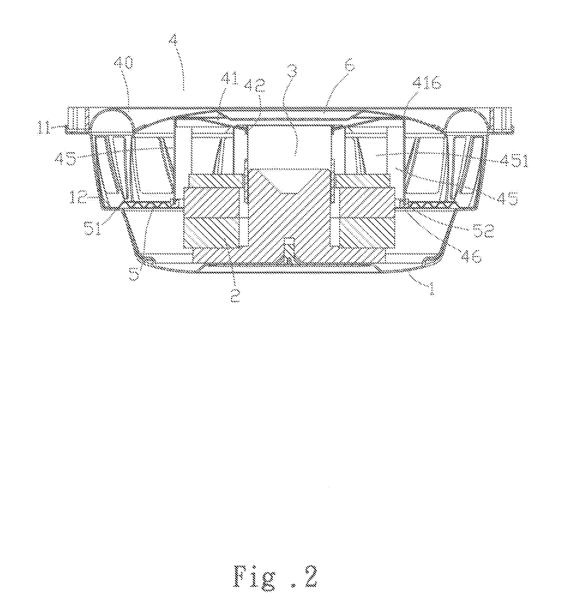
[0016]Please refer to FIGS. 2 to 4. The speaker diaphragm supporting structure according to a preferred embodiment of the present invention includes a basket 1 defining a flared front opening 11 and an internal shoulder portion 12, and having annular magnet 2 mounted to a bottom thereof; a voice coil 3 located in the annular magnet 2; a diaphragm 4 located at the flared front opening 11 with a centered voice coil fixing hole 42 glued to around the voice coil 3; and a flexible suspension member 5 having an outer circumferential edge 51 and an inner circumferential edge 52.

[0017]The speaker diaphragm supporting structure according to the present invention is characterized by the diaphragm 4, which includes a soft suspended flange 40 fixed to the flared front opening 11 of the basket 1, a rigid vibrating membrane 41 having the centered voice coil fixing ho...


PUM


Abstract

A speaker diaphragm supporting structure includes a basket defining a flared front opening and an internal shoulder portion, and having annular magnet mounted to a rear side thereof; a voice coil located in the annular magnet; a diaphragm including a soft suspended flange for fixing to the flared front opening of the basket, a rigid vibrating membrane having a centered voice coil fixing hole for gluing to around the voice coil, a plurality of supporting legs integrally formed on a rear side thereof and a fixing ring portion glued to rear ends of the supporting legs; and a flexible suspension member having an outer circumferential edge set on the internal shoulder portion of the basket and an inner circumferential edge glued to the fixing ring portion, so that the suspension member is held to around an outer side of the annular magnet.

Description

FIELD OF THE INVENTION[0001]The present invention relates to a speaker diaphragm supporting structure, and more particularly to a speaker diaphragm that includes a plurality of supporting legs integrally formed on a rear side thereof, so that the diaphragm has increased structural strength with reduced gluing positions, which enables accurate alignment of speaker components with one another, simplified assembling procedures and accordingly convenient assembling of the speaker to largely increase the rate of yield of the speaker, and the produced speaker can work normally to output good sound quality without becoming failed easily.BACKGROUND OF THE INVENTION[0002]With the quick development in the technological fields, novel and improved audio and visual (A / V) apparatus are constantly introduced into the market, and consumers also have constantly increased demand on the sound quality of the market available A / V apparatus. While the A / V apparatus must be of high quality, the speakers s...

Claims


Application Information

Patent Timeline
Patent Type & Authority Applications(United States)
IPC IPC(8): H04R7/16
CPCH04R7/16H04R9/025H04R9/043H04R9/045H04R31/006H04R2400/11
Inventor CHOU, YEH-FENG
Owner MEILOON INDAL
Why Eureka
Try Eureka