User interface for a biopsy unit

a biopsy unit and user interface technology, applied in the field of biopsy unit operation, can solve the problems of user facing a more complex situation, stressful mammography breast biopsy procedures, etc., and achieve the effect of facilitating the control of the biopsy unit and enhancing the control method

Active Publication Date: 2016-05-12
KONINKLJIJKE PHILIPS NV
View PDF4 Cites 1 Cited by
  • Summary
  • Abstract
  • Description
  • Claims
  • Application Information

AI Technical Summary

Benefits of technology

[0003]There may thus be a need to provide an enhanced and facilitated way of controlling a biopsy unit.

Problems solved by technology

However, it has been shown that mammography breast biopsy procedures, for example, are stressful situations.
Thus, the user is faced with a more complex situation with regards to the operation of the biopsy system.

Method used


Image

  • User interface for a biopsy unit
  • User interface for a biopsy unit
  • User interface for a biopsy unit

Examples


Embodiment Construction

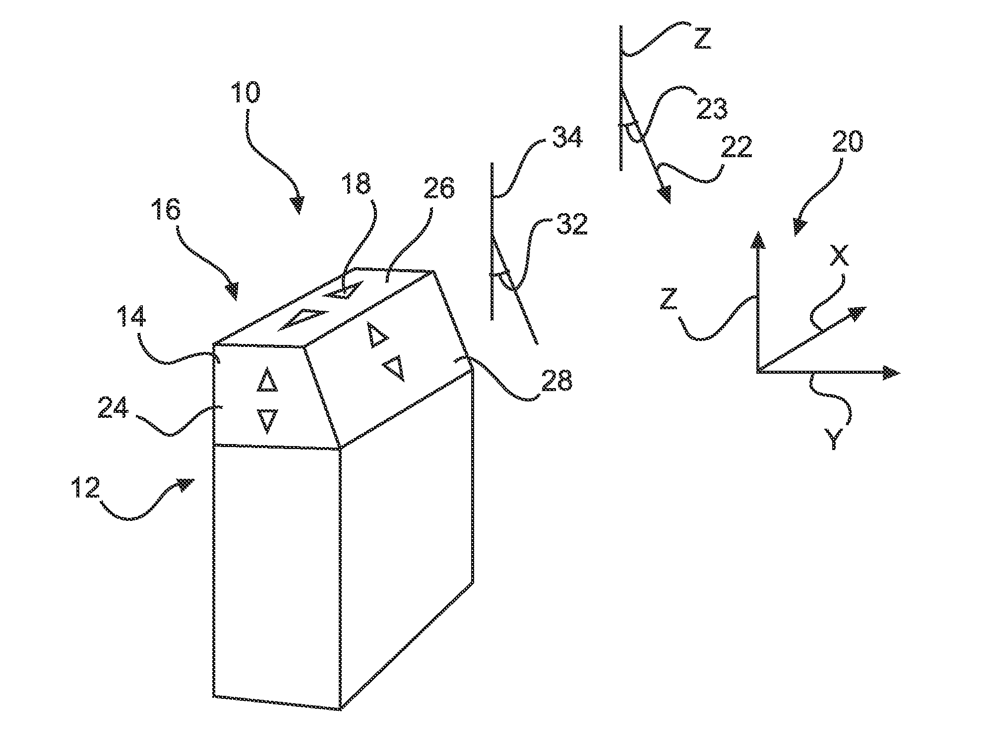
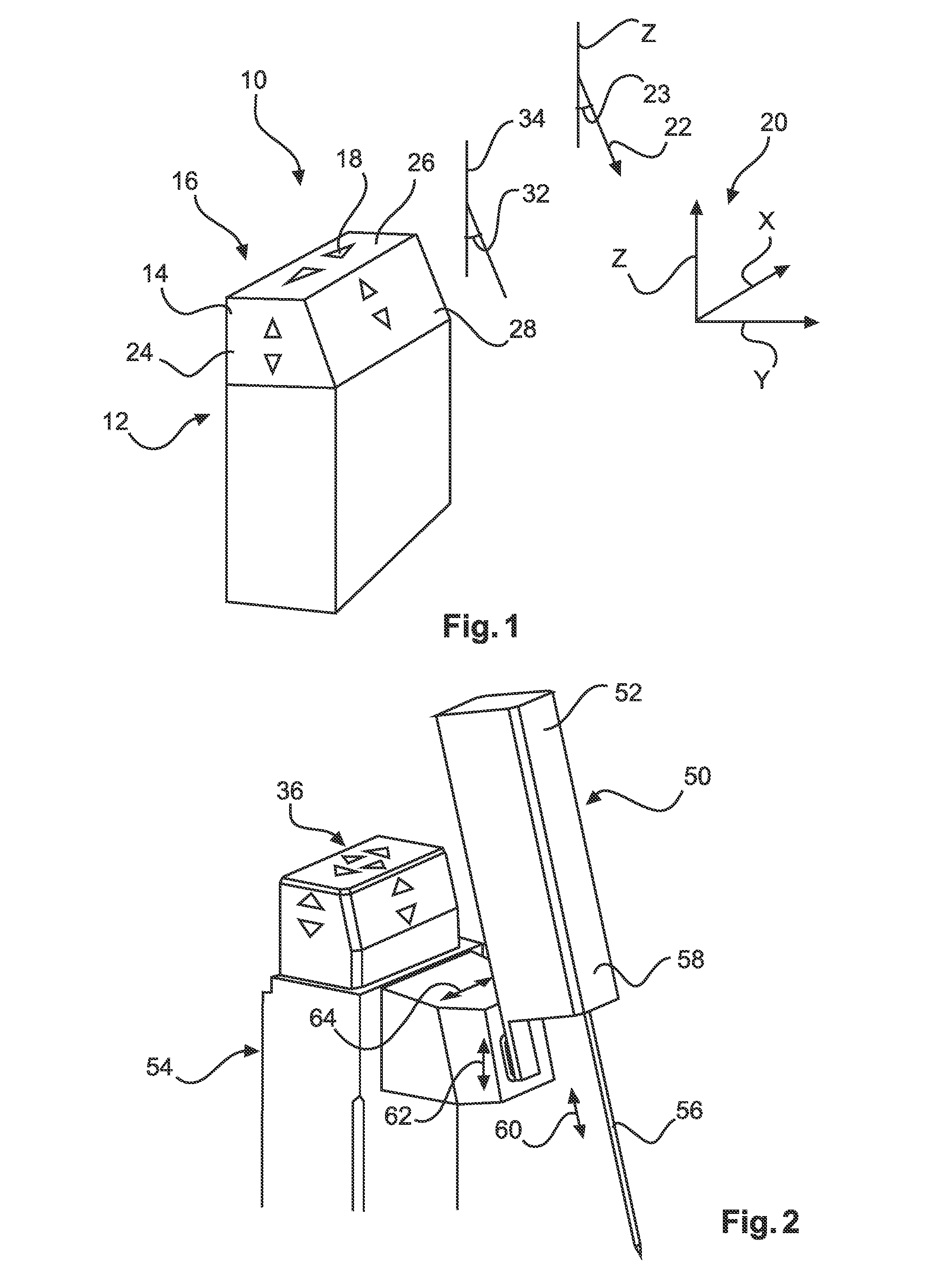
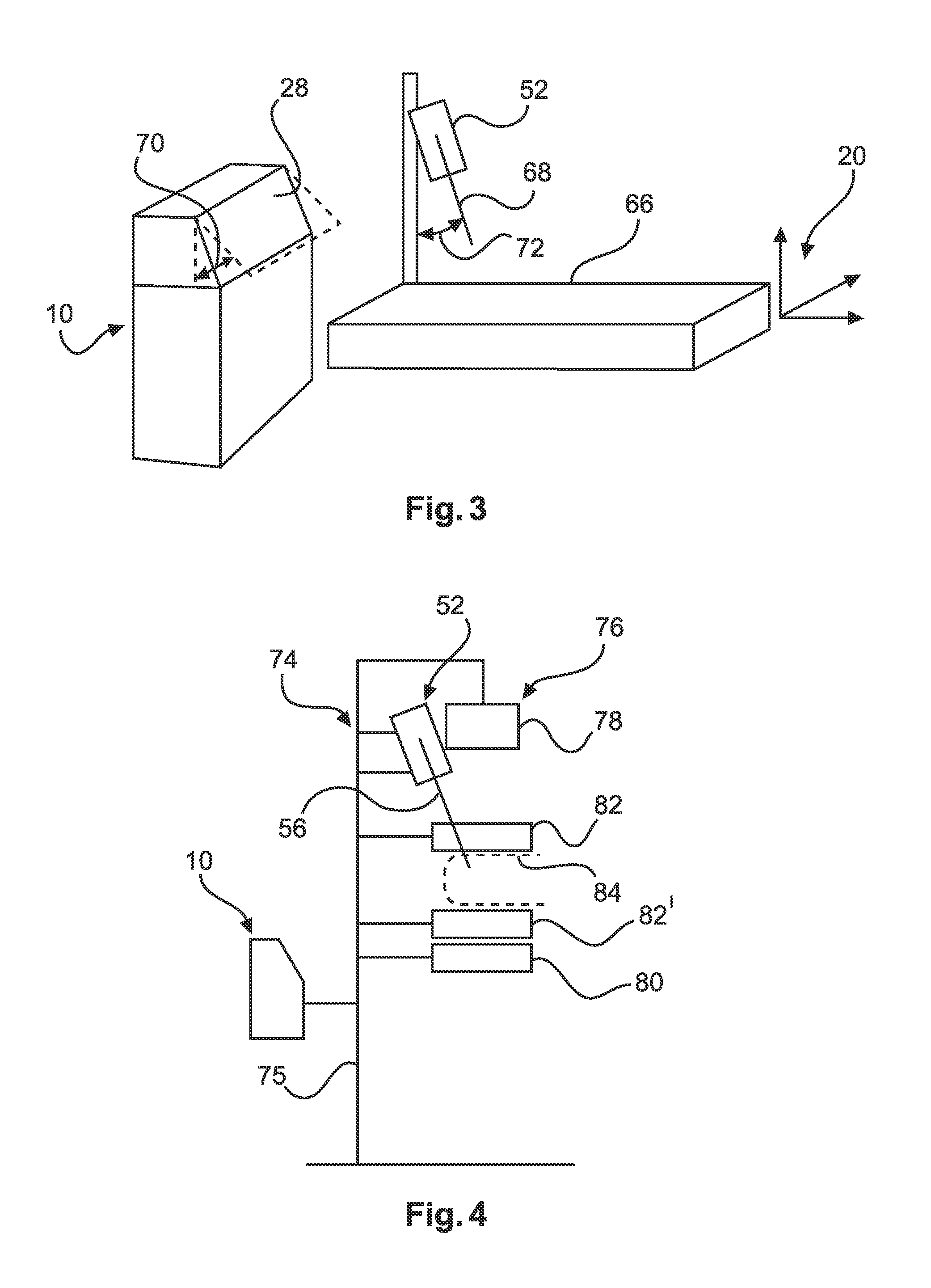
[0031]FIG. 1 shows a control device 10 for controlling a biopsy unit (not further shown). The control device 10 comprises a support structure 12 with a housing 14. Further, a user interface unit 16 with a plurality of control elements 18 is provided. The control elements 18 are configured to control the movement of a biopsy needle device along at least three moving direction lines. At least two of the moving direction lines are aligned to axes of a Cartesian coordinate system 20, as indicated in FIG. 1. One moving direction line is aligned to a needle axis direction 22 of an elongated needle device of the biopsy unit. The needle axis direction is inclined to at least one of the axes of the Cartesian coordinate system.

[0032]The term “biopsy needle device” relates to biopsy needles or other interventional equipment.

[0033]For example, the Cartesian coordinate system 20 may comprise a first z-axis, a second x-axis, and a third y-axis. As indicated by angle symbol 23, the needle axis dir...


PUM


Abstract

The present invention relates to operating a biopsy unit. In order to provide an enhanced and facilitated way of controlling a biopsy unit, a control device (10) for controlling a biopsy unit is provided that comprises a support structure (12) with a housing (14), and a user interface unit (16) with a plurality of control elements (18). The control elements are configured to control the movement of a biopsy needle device along at least three moving direction lines. At least two of the moving direction lines are aligned to axes of a Cartesian coordinate system (20) and one moving direction line is aligned to a needle axis direction (22) of an elongated needle device of the biopsy unit, the needle axis direction being inclined to at least one of the axes of the Cartesian coordinate system. For each moving direction line, the housing is provided with a surface portion (24, 26, 28) that is aligned with a respective one of the moving direction lines. The control element for each moving direction line is arranged on the housing on a respective one of the surface portions; the control element for the movement along the needle axis direction being provided on an inclined surface portion (28) that is aligned with the inclined needle axis direction.

Description

FIELD OF THE INVENTION[0001]The present invention relates to operating a biopsy unit, and relates in particular to a control device for controlling a biopsy unit, to a biopsy system, and to a method for controlling a biopsy unit.BACKGROUND OF THE INVENTION[0002]Biopsy is used in relation with breast examinations, and in particular with mammography interventions. For mammography breast biopsy procedures, a biopsy needle is controlled by a user, for example via control buttons, to adjust the needle coordinates. For example, control buttons are provided for three axes of a Cartesian coordinate system. However, it has been shown that mammography breast biopsy procedures, for example, are stressful situations. Further, an increasing use of inclined needle positions exists, for example in combination with X-ray imaging systems that lead to certain space restrictions. Thus, the user is faced with a more complex situation with regards to the operation of the biopsy system.SUMMARY OF THE INV...

Claims


Application Information

Patent Timeline
Patent Type & Authority Applications(United States)
IPC IPC(8): A61B34/00A61B6/00A61B90/11A61B10/00A61B10/02
CPCA61B34/25A61B10/0041A61B6/502A61B90/11A61B10/0233A61B2017/3409
Inventor GUNEE, ANDERS RICHARDMYRMAN, PER MATTIAS
Owner KONINKLJIJKE PHILIPS NV
Why Eureka
Try Eureka