Mixed Stator for an Axial Turbine Engine Compressor

a technology of axial turbine engine and stator, which is applied in the direction of machines/engines, stators, liquid fuel engines, etc., can solve the problem of limited rigidity of assembly

Active Publication Date: 2016-05-12
TECHSPACE AERO
View PDF7 Cites 15 Cited by
  • Summary
  • Abstract
  • Description
  • Claims
  • Application Information

AI Technical Summary

Problems solved by technology

However, the rigidity of th

Method used


Image

  • Mixed Stator for an Axial Turbine Engine Compressor
  • Mixed Stator for an Axial Turbine Engine Compressor
  • Mixed Stator for an Axial Turbine Engine Compressor

Examples


Embodiment Construction

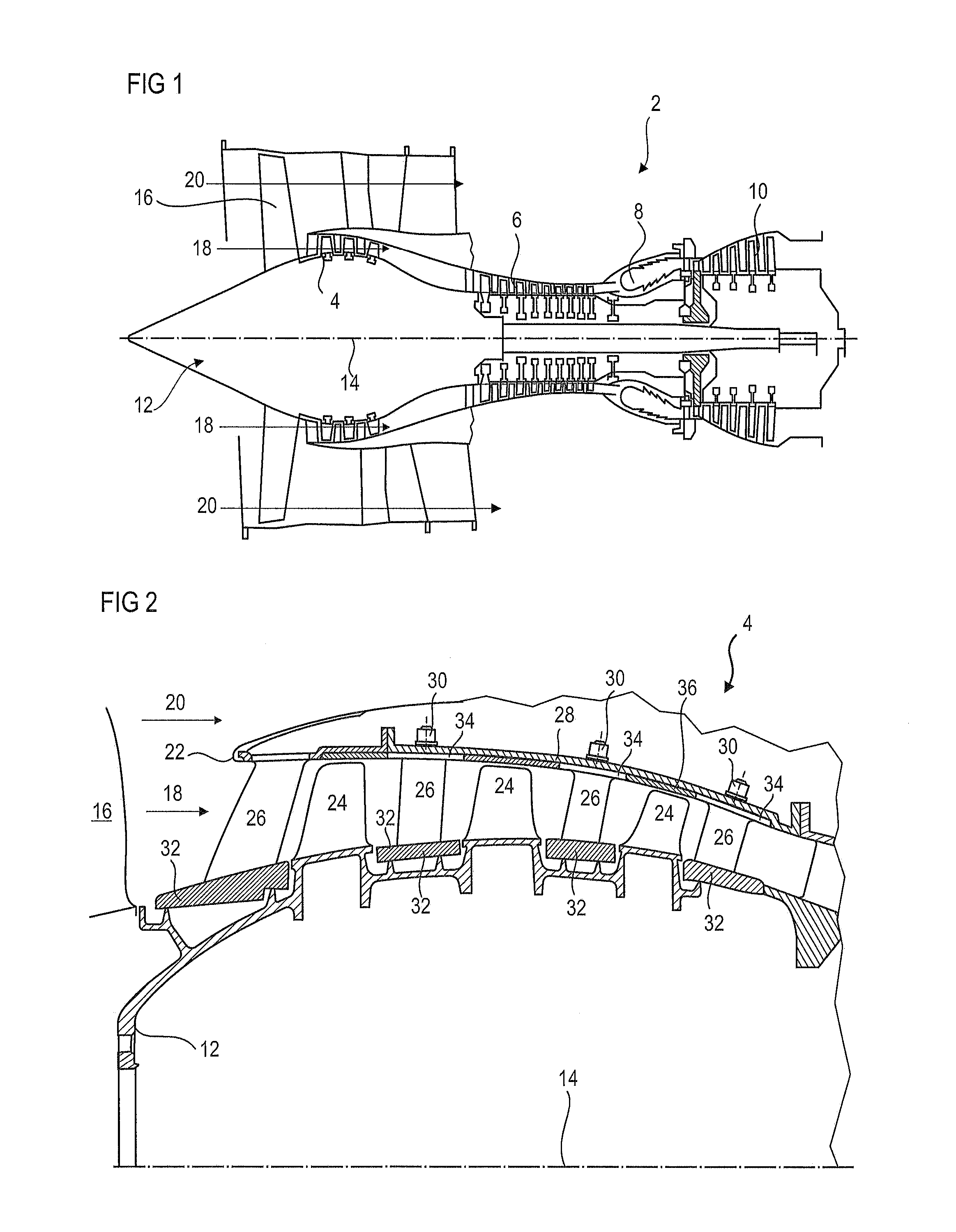
[0014]The present application aims to solve at least one of the problems presented by the prior art. More specifically, an object of the present application is to improve the rigidity of an axial turbine engine stator comprising an annular row of vanes. An object of the present application is also to improve the axial retention of internal shrouds which are fitted between structuring turbine vanes of an axial turbine engine stator.

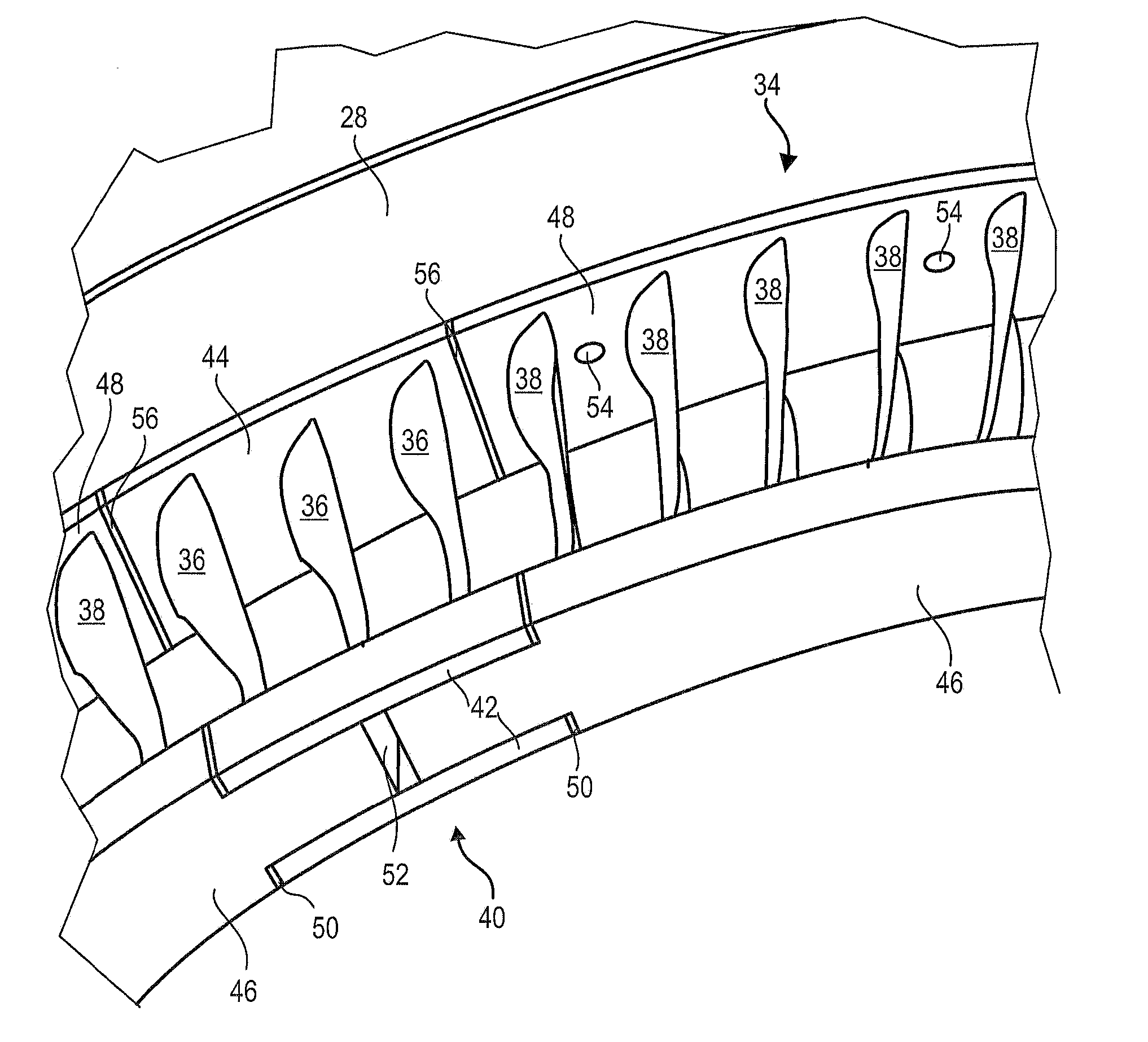
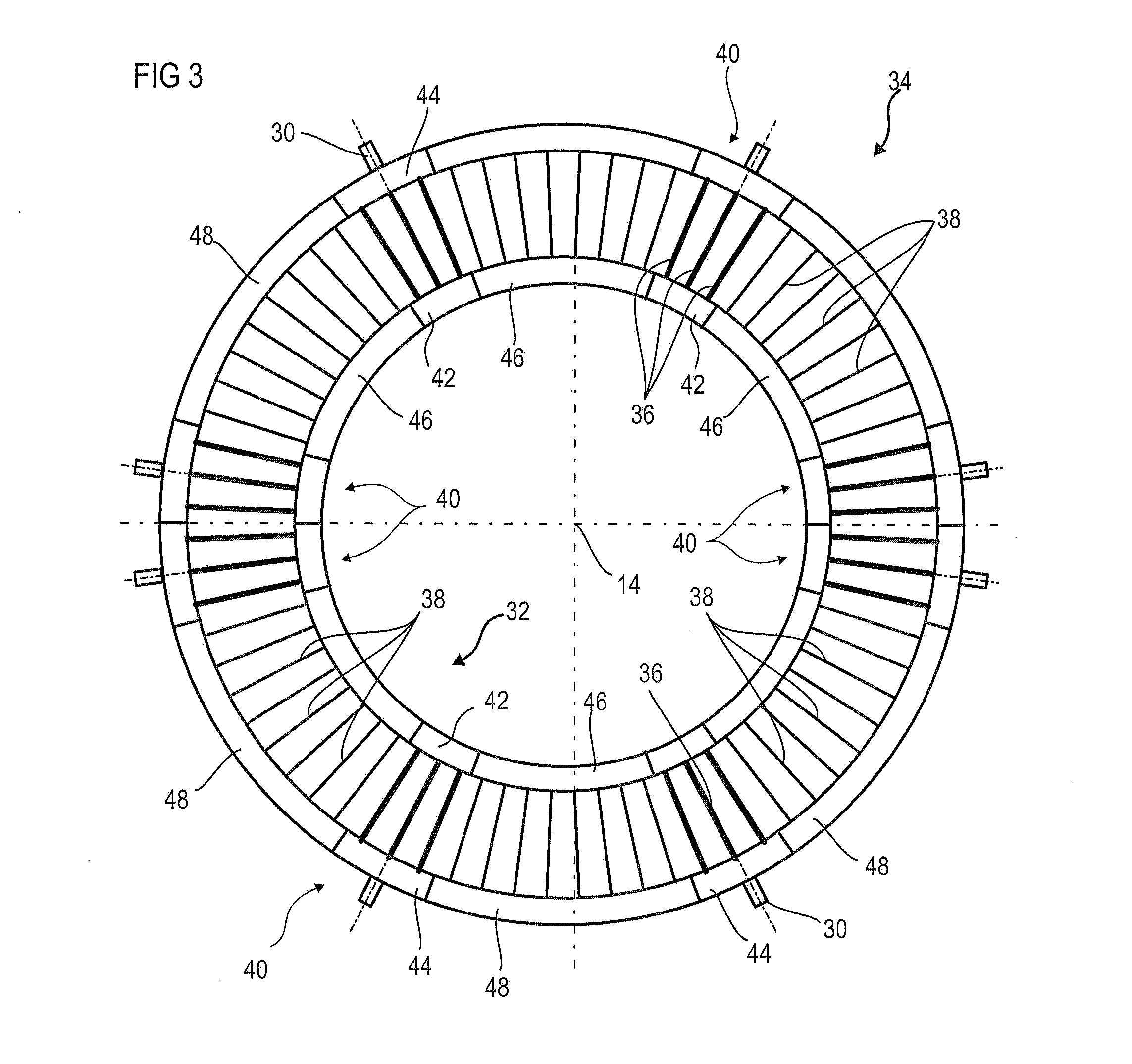
[0015]It will be appreciated that the present application provides an axial blocking between a support vane and a segment of internal shroud as a result of facets which are orientated in an upstream direction and / or in a downstream direction, the facets being at one or each interface between a support vane and a shroud segment.

[0016]The present application relates to a stator for an axial turbine engine, in particular a compressor, the stator comprising: an annular row of stator vanes which comprise integral support vanes with internal platforms, and conne...


PUM


Abstract

The present application relates to a stator for a low-pressure compressor of an axial turbine engine. The stator includes an annular row of stator vanes with connection vanes, and support vanes which are grouped into vaned casings. The casings include internal platforms and external platforms, and are integrally produced by means of additive production based on titanium powder. The stator has a circular internal shroud which is formed by the internal platforms of the vanes of the casings and internal shroud segments which are fixed to the connection vanes. The internal platforms include pairs of contact surfaces in order to interlock the shroud segments therein by moving into abutment and sliding against the contact surfaces. The contact surfaces are perpendicular to the rotation axis and form axial stops.

Description

BACKGROUND[0001]1. Field of the Application[0002]The present application relates to turbine engines, in particular turbojets for aircraft. The present application more specifically relates to a stator architecture of an axial turbine engine.[0003]2. Description of Related Art[0004]A turbine engine currently has a plurality of annular rows of stator vanes with various architectures. These rows are distinguished by their methods for fixing the vanes to each other, or even the type of connection with an outer housing which supports each vane. In order to channel a primary flow and to ensure sealing with respect to the rotor, a row generally supports an internal shroud which is fixed to the inner ends of the stator vanes. These shrouds are subjected to significant axial forces, in the context of a low-pressure compressor they are subjected to pumping phenomena or occurrences of ingestion.[0005]Document EP2339120A1 discloses an architecture for a low-pressure compressor rectifier of an a...

Claims


Application Information

Patent Timeline
IPC IPC(8): F01D9/04F01D25/24F01D9/06F01D5/02F01D11/12
CPCF01D9/041F01D5/02F01D11/122F01D9/06F05D2300/603F05D2220/323F05D2240/12F05D2240/24F01D25/246F01D9/042F04D29/541F05D2300/40F04D29/542Y02T50/60
Inventor CORTEQUISSE, JEAN-FRANCOIS
Owner TECHSPACE AERO
Why Eureka
Try Eureka