This helps you quickly interpret patents by identifying the three key elements:
Problems solved by technology
Method used
Benefits of technology
Benefits of technology
This patent describes a check valve for a hydrogen tank, which has a simplified structure and reduces the pressure loss. The valve has a sealing portion that is formed in its outer surface, which seals the flow path between the valve housing and the casing, positioning the valve housing in the radial direction perpendicular to the casing. The check valve also has a receptacle structure that includes the check valve and an interposition member to prevent corrosion of the valve and improve its durability. The invention reduces the exposure of components of the check valve to the flow path, improving the efficiency of the check valve and reducing the pressure loss.
Problems solved by technology
In other words, it is necessary to form the particular structure for forming the flow path by cutting etc., thereby requiring a complicated manufacturing process.
Method used
Image
Click on the blue label to locate the original text in one second.
Reading with bidirectional positioning of images and text.
Examples
modification 1
Modification of Sealing Portion
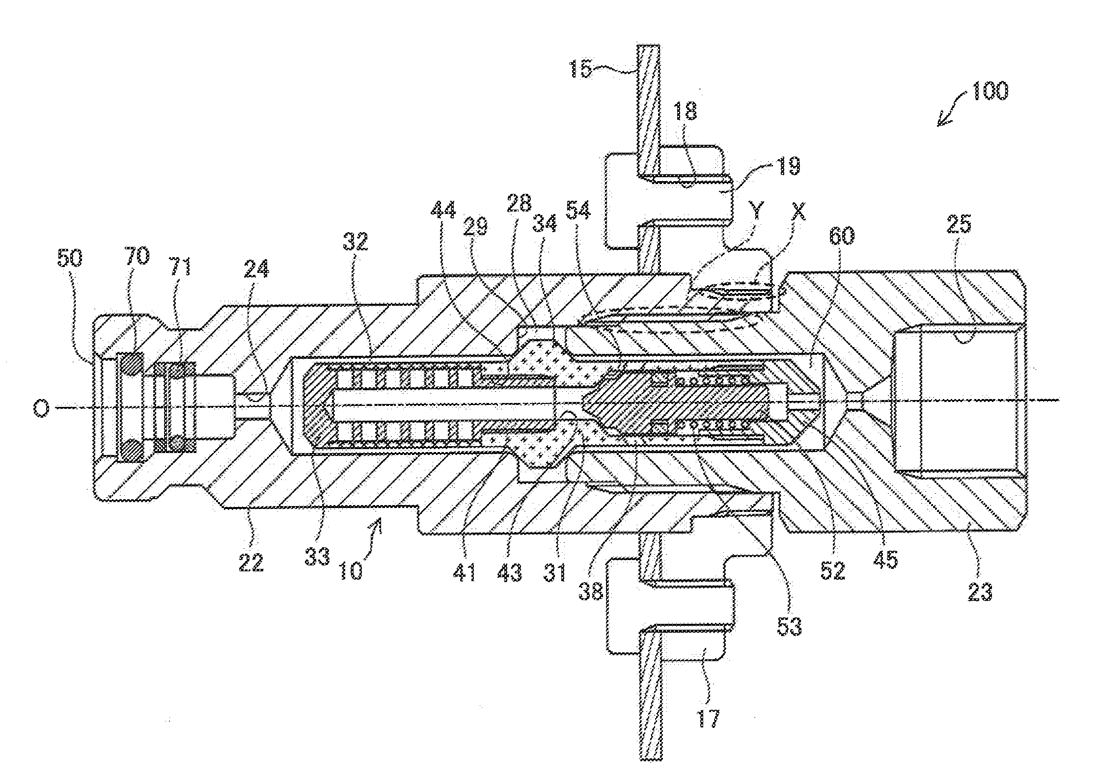
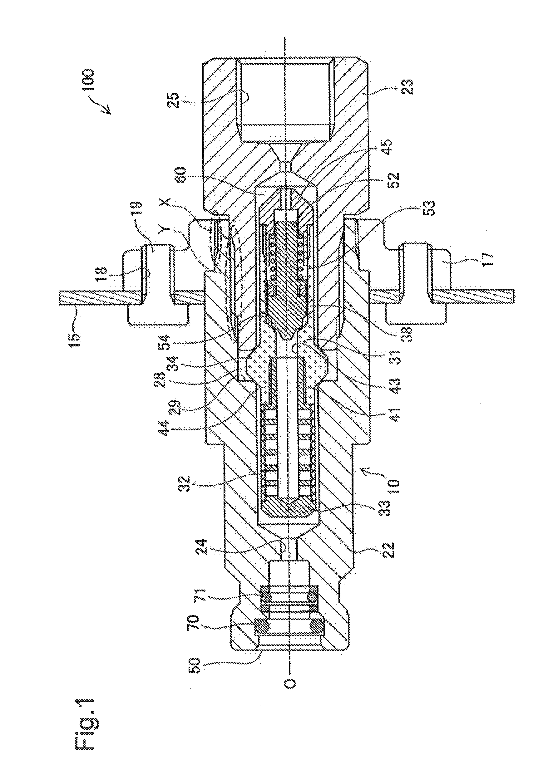
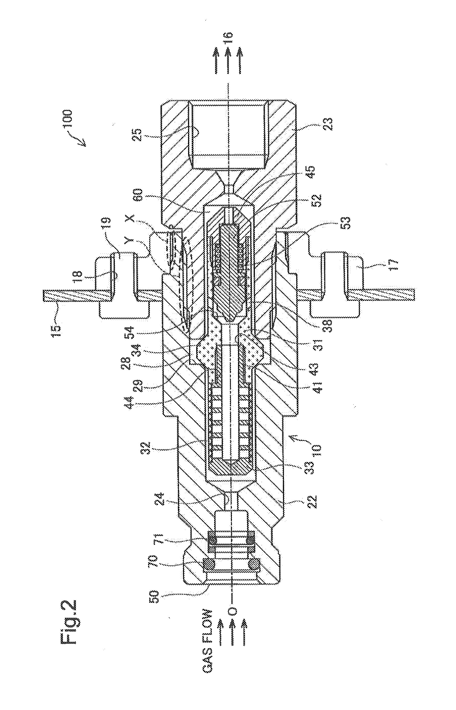
[0063]Although the casing flow path 60 formed between the casing 20 and the subassembly 30 is metal-sealed in the above embodiment described using the protruded portion 34, different structures may also be adopted. For example, the seal described above may be comprised of an O-ring or a resin seal which are provided separately from the valve housing 31.
[0064]FIG. 7 is a cross-sectional view illustrating a receptacle structure 200 provided with a check valve 210 of this modification. In FIG. 7, a state where the check valve is open, similar to FIG. 2, is illustrated. In this modification, the same reference numerals are given to parts which are common to the parts of the receptacle structure 100 described in the embodiment, and detailed description thereof is thus omitted.
[0065]A protruded portion 234 is formed in an outer surface of a valve housing 231 provided to the check valve 210, instead of the protruded portion 34. The protruded portion 234 is pi...
modification 2
Modification of Subassembly
[0068]Although the filter 32 is compressed and held by the filter supporting portion 39 of the filter guide 33 and the tip-end supporting portion 46 of the valve housing 31 in the embodiment, different structures may also be adopted. For example an end portion of the filter 32 may be fixed to the filter guide 33 by welding, without providing at least one of the filter supporting portion 39 having the flange-shaped structure and the tip-end supporting portion 46 for holding the filter 32. By having such a structure, similar effects of reducing the hydrogen flow which bypasses the filter 32 can also be acquired. Note that, when the filter 32 is pinched and held from both sides similar to the embodiment, it is desirable because particular processes, such as welding, become unnecessary, and only the filter 32 can be replaced at the time of a maintenance, without replacing the filter guide 33. When both ends of the filter 32 in the axial direction are welded, o...
modification 3
Modification of Receptacle Structure
[0072]Although the attachment of the check valve 10 to the flange 17 is achieved by the threaded-engagement fastening in the embodiment (fastening portion X in FIGS. 1 and 2), different structures may also be adopted. For example, the check valve 10 and the flange 17 may be fixed to each other by using a snap ring, etc.
[0073]Although the flange 17 is used as the interposition member which is placed between the check valve 10 and the vehicle body (vehicle body 15) in the embodiment, different structures may also be adopted. For example, the casing 20 and the vehicle body 15 may be directly fastened to each other by using bolts and nuts as the interposition member. Also in such a case, when the interposition member is made of metal which is lower in the ionization tendency than the casing, similar effects of preventing the corrosion of the casing and improving the durability of the check valve 10 can be acquired.
[0074]In the embodiment, although the...
PUM
Property
Measurement
Unit
Length
aaaaa
aaaaa
Diameter
aaaaa
aaaaa
Abstract
In order to reduce a pressure loss in a check valve and simplify a manufacturing process, a check valve (10) configured to be disposed in piping of fluid is provided, which includes a valve housing (31) including a valve element (52) and a valve seat (54) therein, a casing (20) that is configured to place the valve housing therein, in which a casing flow path (60) is provided between the casing and the valve housing to make a flow of the fluid in an axial direction of the valve housing. In the valve housing, a communicating hole (38) and sealing portion (34) are formed. The communicating hole that is formed through the valve housing in a thickness direction thereof introduces the fluid, which flows through between the valve element and the valve seat at the open position of the check valve, into the casing flow path. The sealing portion that is provided on an outer surface of the valve housing upstream of the communicating hole in a flow direction of the fluid in the casing flow path, is configured to come into contact with an inner surface of the casing to seal the casing flow path and position the valve housing in a radial direction perpendicular to the axial direction relative to the casing.
Description
CROSS REFERENCE TO RELATED APPLICATION[0001]This application claims priority to Japanese Patent Application No. 2014-229862, filed on Nov. 12, 2014, the contents of all of which are incorporated herein by reference in their entirety.BACKGROUND[0002]1. Field[0003]The present invention relates to a check valve and a receptacle structure provided with the check valve.[0004]2. Related Art[0005]As a check valve for preventing a back flow of fluid, JP2013-535621A proposes a check valve in which a valve element pressed in a direction opposite from an original flow direction of fluid (closing direction), and a valve element supporting part which surrounds and supports the valve element so as to extend in axial direction of the valve element (moving direction of the valve element) are provided inside a casing, and a flow path through which the fluid flows in the axial direction described above is formed between the valve element supporting part and the casing. The structure in which the flow...
Claims
Application Information
Patent Timeline
Application Date:The date an application was filed.
Publication Date:The date a patent or application was officially published.
First Publication Date:The earliest publication date of a patent with the same application number.
Issue Date:Publication date of the patent grant document.
PCT Entry Date:The Entry date of PCT National Phase.
Estimated Expiry Date:The statutory expiry date of a patent right according to the Patent Law, and it is the longest term of protection that the patent right can achieve without the termination of the patent right due to other reasons(Term extension factor has been taken into account ).
Invalid Date:Actual expiry date is based on effective date or publication date of legal transaction data of invalid patent.

