Quick connect pneumatic coupler

a pneumatic coupler and quick technology, applied in the field of components, can solve the problems of compromising the integrity of the same, inefficient processes, compromising and/or permanently damaging the wall and/or toolbar,

Inactive Publication Date: 2016-05-12
KINZE MFG INC
View PDF12 Cites 6 Cited by
  • Summary
  • Abstract
  • Description
  • Claims
  • Application Information

AI Technical Summary

Benefits of technology

[0008]It is therefore a primary object, feature, and / or advantage of the present invention to improve on or overcome the deficiencies in the art.
[0009]It is another object, feature, and / or advantage of the present invention to permit installation of a pneumatic coupler without access to the interior of the toolbar or otherwise backside of a surface.
[0010]It is another object, feature, and / or advantage of the present invention to provide a pneumatic coupler that does not require invasive installation methods to preserve the integrity of the bung, planter tube wall and / or toolbar.
[0011]It is yet another object, feature, and / or advantage of the present invention to provide a pneumatic coupler to accommodate toolbars and / or planter tube walls of different thicknesses.
[0012]It is still another object, feature, and / or advantage of the present invention to provide an improved method of connecting a pneumatic coupler to a toolbar of an agricultural implement.
[0013]It is a further object, feature, and / or advantage of the present invention to provide a sealing member positioned between a bung nut and the exterior of the planter tube wall to provide a seal.

Problems solved by technology

The process is cumbersome and may alter the material properties of the welded area of the bung and / or wall, possibly compromising the integrity of the same.
Likewise, if a bung needs to be replaced, the welded bung must be chiseled, grinded or torched, processes that are also inefficient and may compromise and / or permanently damage the wall and / or toolbar.
Moreover, other modes of installation of a pneumatic coupler often require the user have physical access to the inside surface of the wall.
Given the space constrains of toolbars and agricultural machine implements generally, gaining access and clearance to effectively work on the inside surface of the wall may be unachievable.
Pneumatic couplers utilizing a two-piece construction, whereby male and female portions are mated through an aperture on opposite sides of the planter tube wall, do not accommodate toolbars and planter tube walls of significantly different thicknesses.
As a result, an individual seeking to install or change a pneumatic coupler may need to maintain an inventory of different sized couplers with associated inconvenience and expense.

Method used


Image

  • Quick connect pneumatic coupler
  • Quick connect pneumatic coupler
  • Quick connect pneumatic coupler

Examples


Embodiment Construction

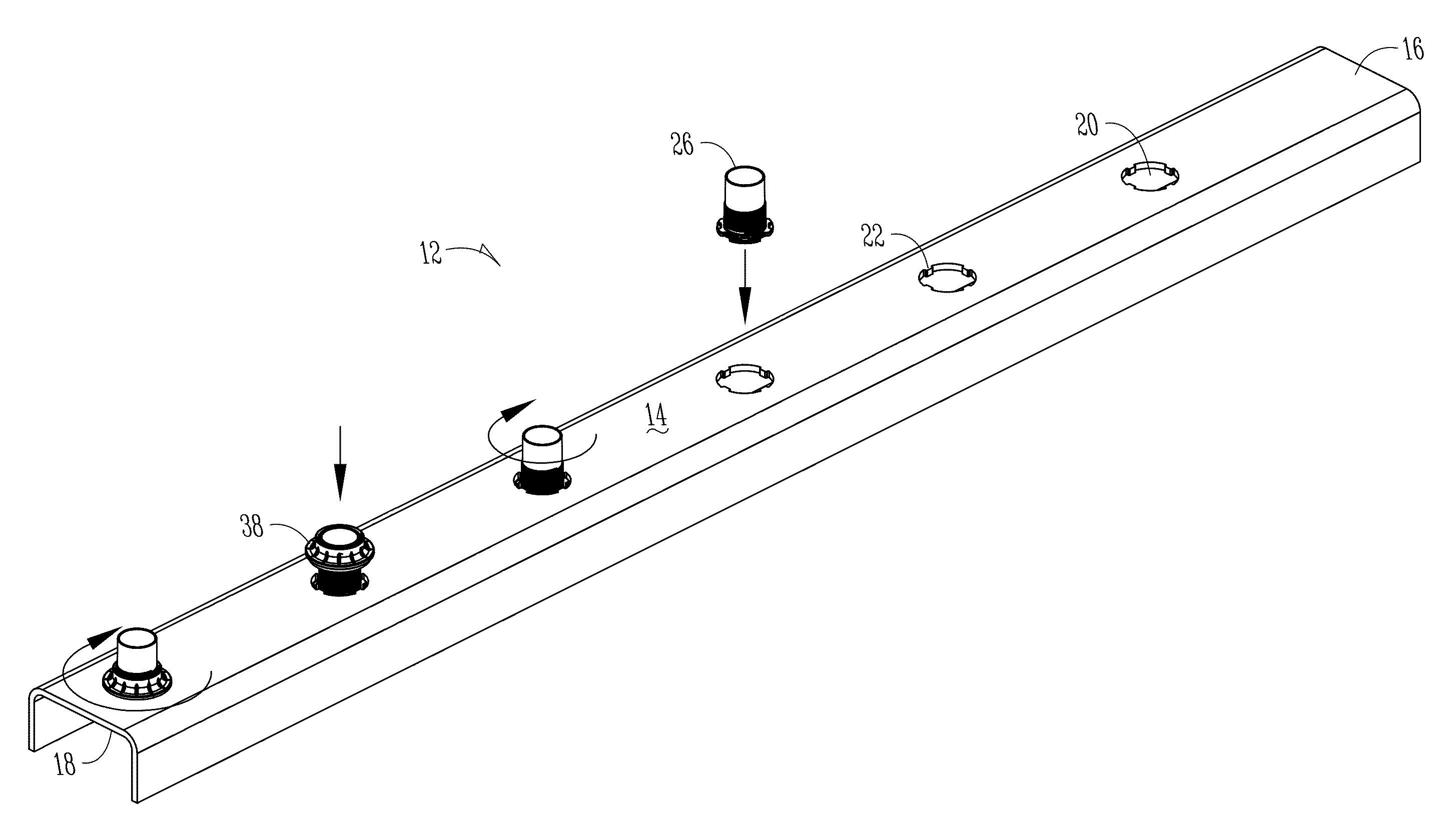
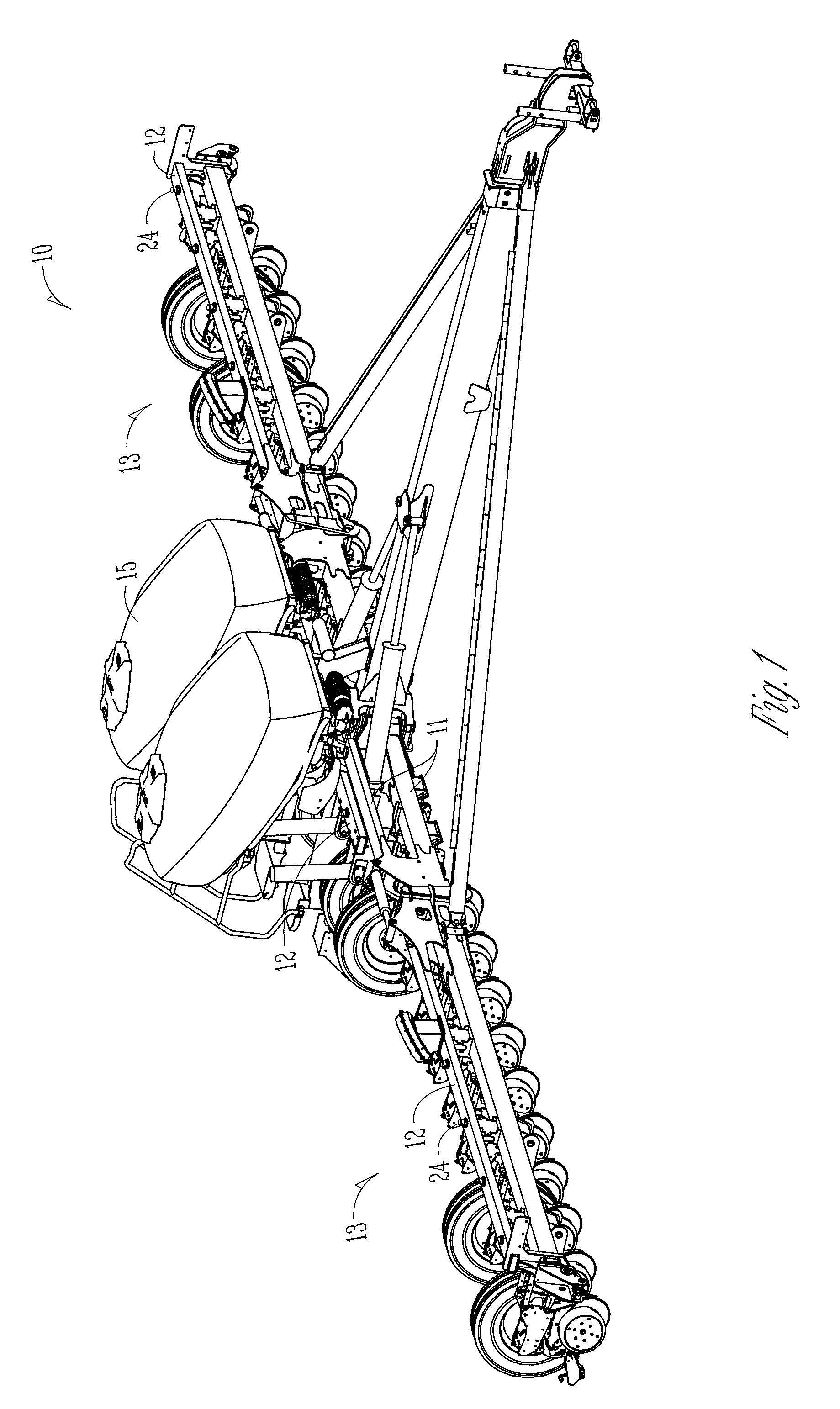
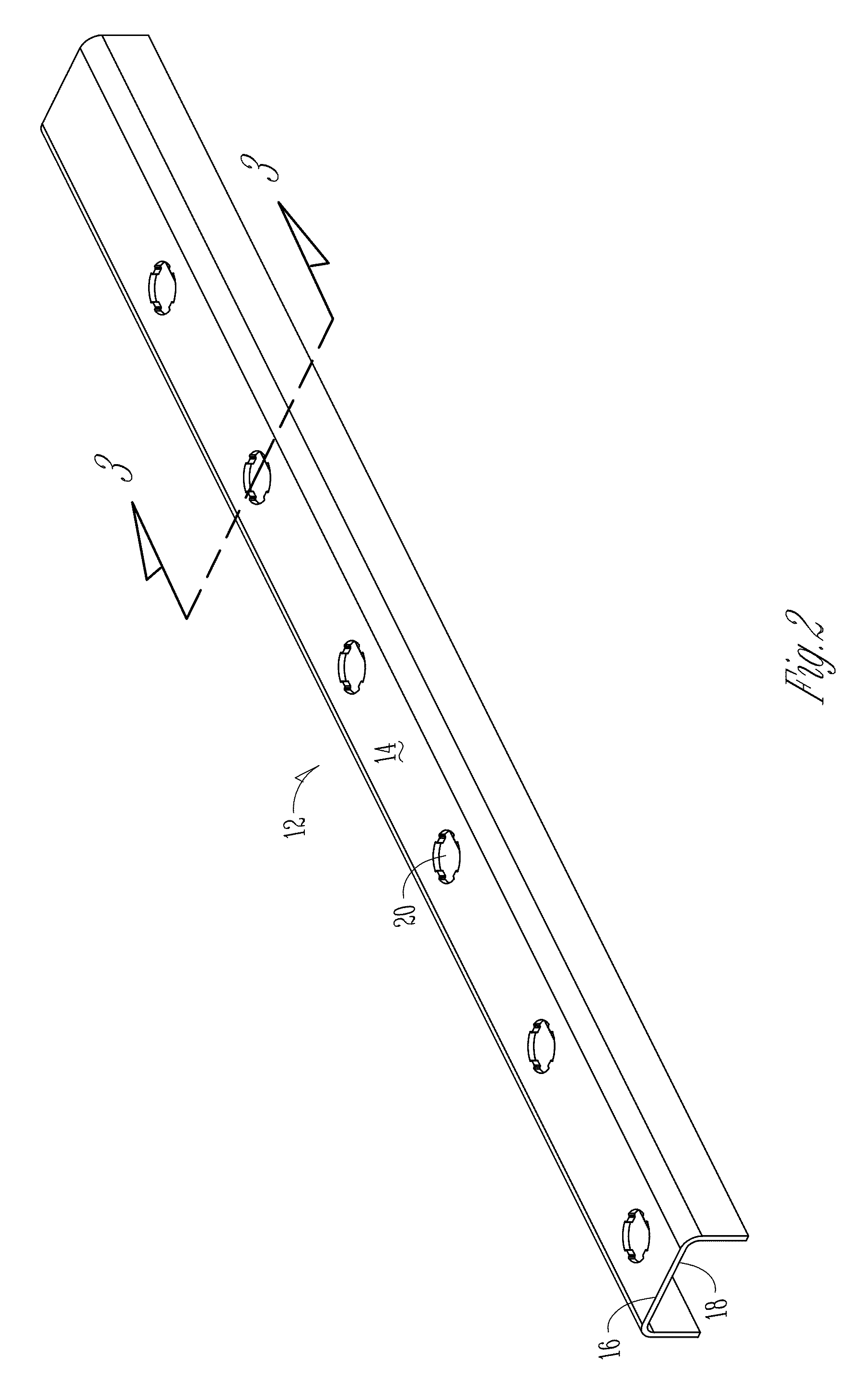
[0032]FIG. 1 shows a conventional planter implement 10. While the figure shows a planter, it should be appreciated by those skilled in the art that the invention covers other types of implements, including but not limited to, nutrient applicators, plows, discs, air seeders, and other agricultural equipment. The implement 10 may include a central frame 11, to which numerous components of the implement 10 may be connected, including but not limited to, left and right wings 13, hoppers 15, pumps, seed meters, and toolbars 12. The wings 13 may also have toolbars 12. Pneumatic couplers 24 of the present invention may be connected to the toolbars 12. However, the present invention contemplates that the pneumatic couplers may be connected to any substantially planar structure requiring interfacing with pneumatic hoses (not shown).

[0033]For example, the wings and central tool bar may include row units attached thereto. The row units can include ground-engaging and / or particulate supplying d...


PUM

PropertyMeasurementUnit
elastomericaaaaaaaaaa
thicknessaaaaaaaaaa
circumferenceaaaaaaaaaa

Abstract

A pneumatic coupler and method for coupling a hose to a surface of an agricultural implement is provided. The pneumatic coupler includes a hollow tube with a radially extending flange. The flange has one or more cutouts to permit the flange to pass through an aperture containing one or more protrusions. The flange has one or more recesses to mate with the one or more protrusions to mitigate rotation of the pneumatic coupler relative to the surface. A nut connects to the hollow tube and at least partially surrounds the hollow tube. A sealing member disposed between the flange and the nut provides a seal at the aperture of the surface.

Description

FIELD OF THE INVENTION[0001]The present invention relates generally to components used in agricultural planting implements for dispensing seeds. More particularly, but not exclusively, the invention relates to the installation of pneumatic hoses to toolbars of agricultural planting implements in pneumatic seed meter systems.BACKGROUND OF THE INVENTION[0002]A seed meter is a mechanism installed on agricultural planting implement to accurately and precisely distribute seed into the ground. The seed meter may be designed to deposit a singular seed at predetermined intervals along a seed trench. In such instances, the seed meter is designed to limit, and preferably eliminate, depositing more than one seed at a given interval (i.e., “multiples”) and failing to deposit a seed (i.e., “skips”) to promote a uniform emergence of plants.[0003]Several types of seed meters systems exist, including but not limited to, brush-type, mechanical finger, and pneumatic. Pneumatic seed meters utilize pos...

Claims


Application Information

Patent Timeline
Patent Type & Authority Applications(United States)
IPC IPC(8): F16L41/08A01C7/08
CPCA01C7/082F16L41/08F16L41/14
Inventor LIND, RILEYWILHELMI, MATTHEW J.
Owner KINZE MFG INC
Why Eureka
Try Eureka