
Drywall brace and method for installing

a brace and drywall technology, applied in the field of braces, can solve the problems of relative large aperture in the drywall sheet and also structurally not particularly strong, and achieve the effects of low cost, mass production, and wide application

Inactive Publication Date: 2016-05-12
ROBERTS JAMES
View PDF1 Cites 4 Cited by
  • Summary
  • Abstract
  • Description
  • Claims
  • Application Information

AI Technical Summary

Benefits of technology

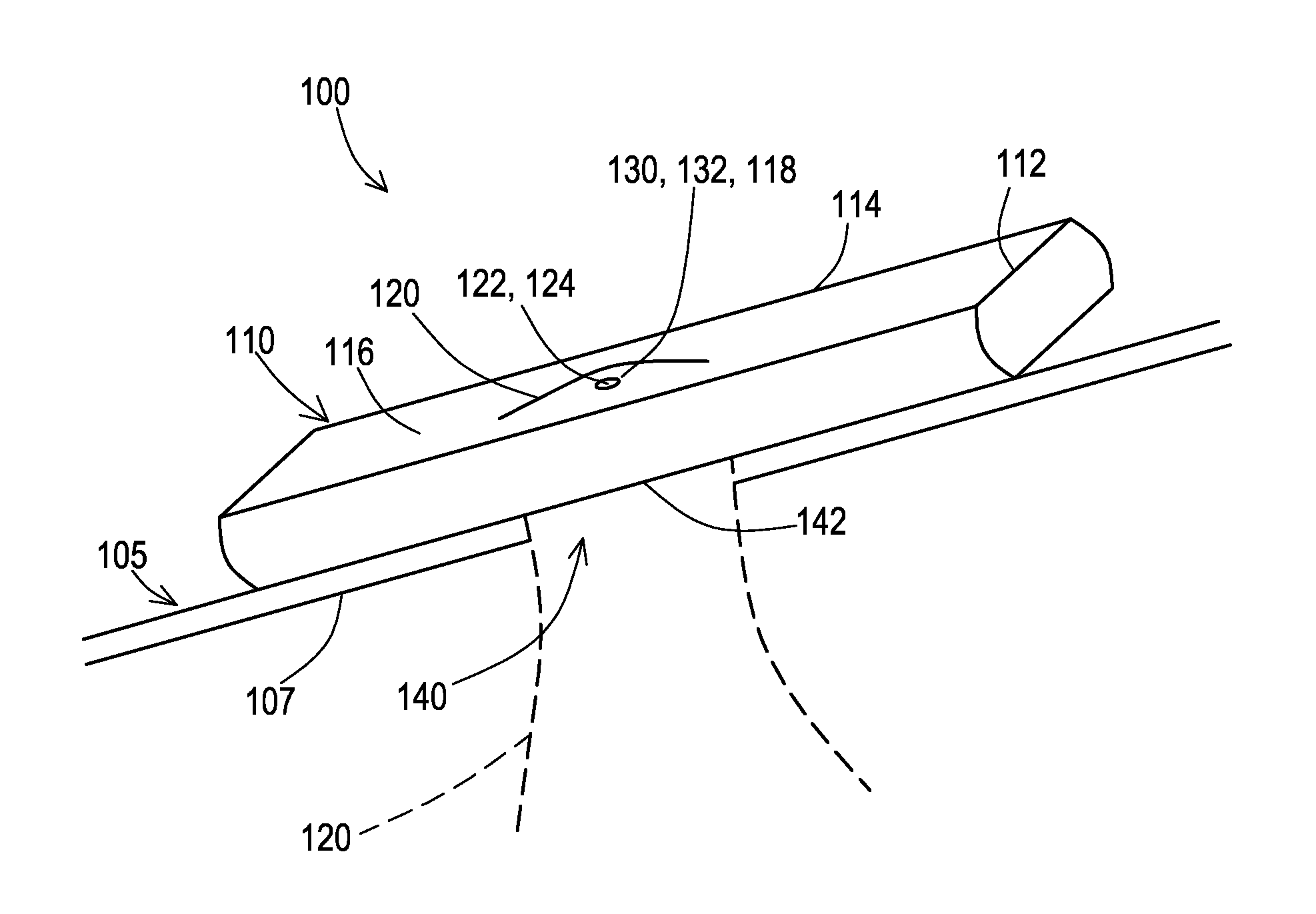
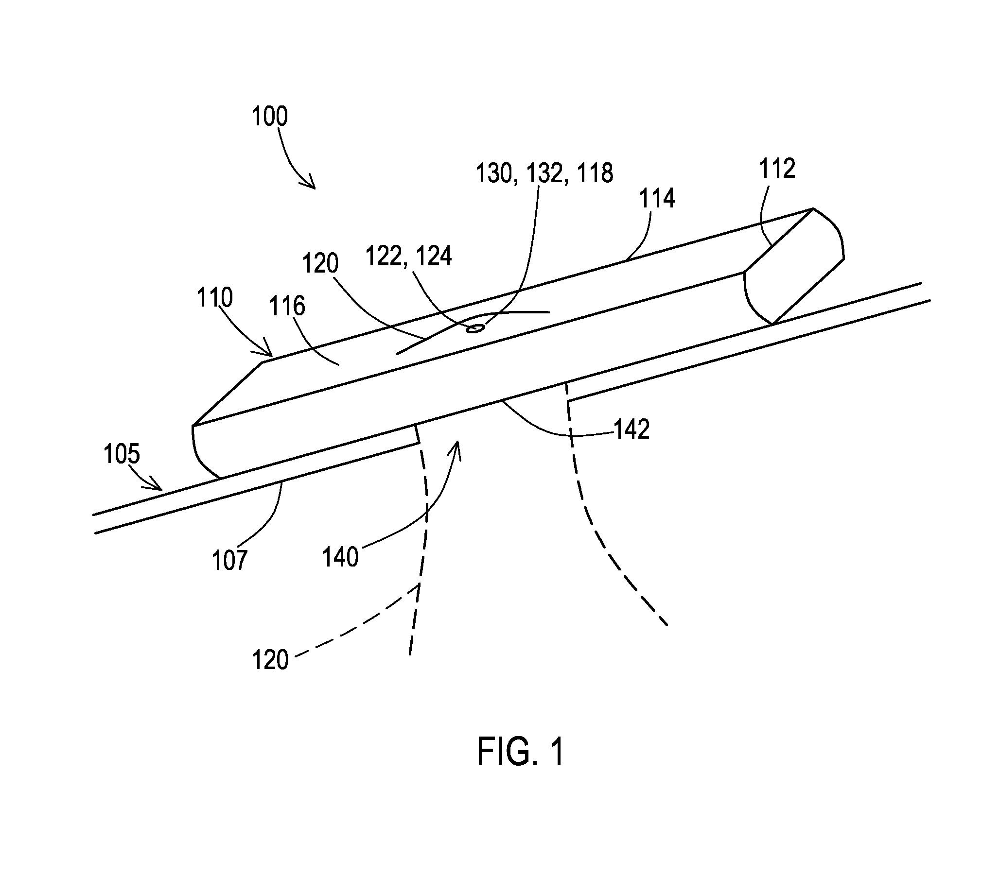
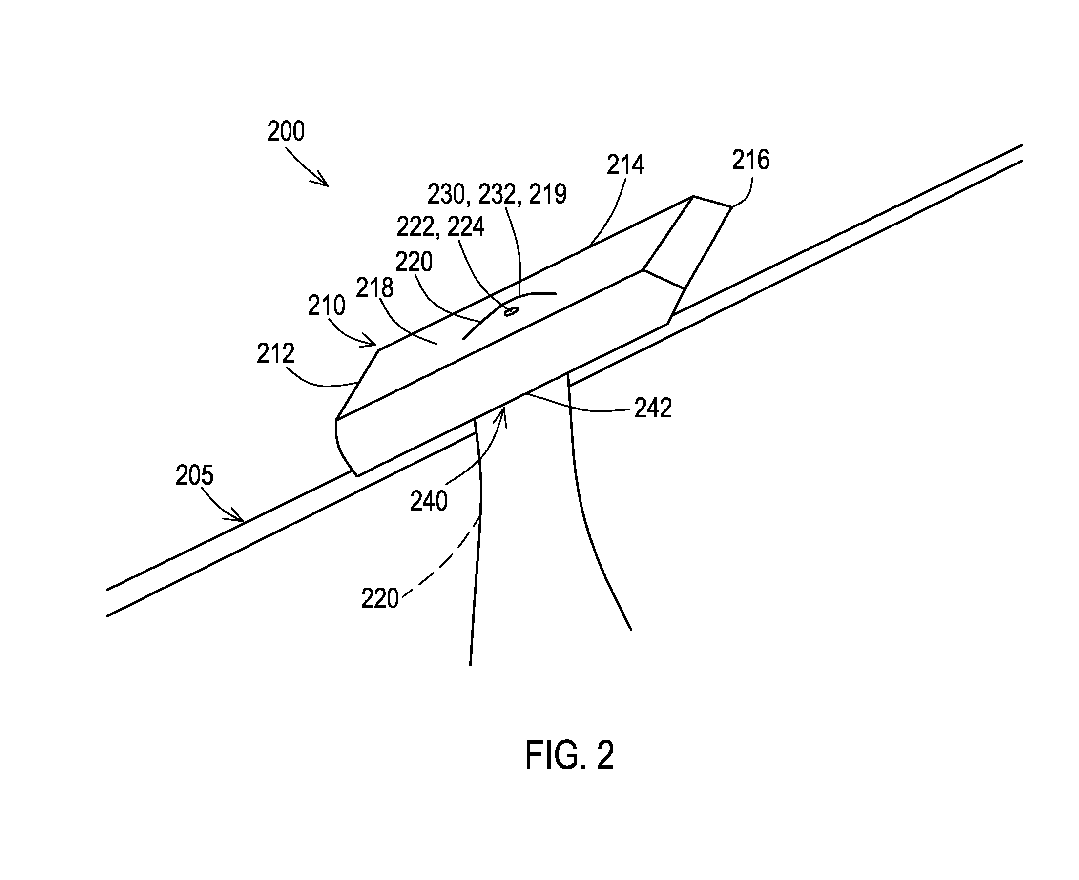
The present invention provides a drywall brace that allows for mounting appliances on a sheet of drywall without making a large aperture in the sheet. This results in higher fortification over traditional methods while maintaining the aesthetic appearance of the sheet of drywall. The drywall brace is uncomplicated, has wide application, and can be mass produced at a relatively low cost. No training is required for installers.

Problems solved by technology

These applications produce a relatively large aperture in the sheet of drywall and are also structurally not particularly strong.

Method used


Image

  • Drywall brace and method for installing
  • Drywall brace and method for installing
  • Drywall brace and method for installing

Examples


Embodiment Construction

[0018]Various aspects of the illustrative embodiments will be described utilizing terms commonly employed by those skilled in the art to convey the substance of their work to others skilled in the art. However, it will be apparent to those skilled in the art that the present invention may be practiced with only some of the described aspects. For purposes of explanation, specific numbers, materials and configurations are set forth in order to provide a thorough understanding of the illustrative embodiments. However, it will be apparent to one skilled in the art that the present invention may be practiced without the specific details. In other instances, well-known features are omitted or simplified in order not to obscure the illustrative embodiments.

[0019]Various operations will be described as multiple discrete operations, in turn, in a manner that is most helpful in understanding the present invention, however, the order of description should not be construed as to imply that thes...


PUM


Abstract

A drywall brace that is a bar that is flattened on at least one side, with a thin, line or wire such as a multi-strand wire strategically attached on both sides of a mounting aperture in the bar. The thin strand wires are at least as long as two-thirds of the length of the bar. The drywall brace is pushed through an aperture in the sheet of drywall lengthwise, either end first. The flat side of the drywall brace is positioned against the sheet of drywall. The thin line or wire is utilized to position the drywall brace and to hold the thin line or wire until a fastener such as a screw is mounted into the drywall brace. Prior to inserting the drywall brace through the sheet of drywall, a pilot aperture is drilled into the drywall brace midway between the mounting locations of the thin line or wire.

Description

BACKGROUND OF THE INVENTION[0001]1. Field of the Invention[0002]The present invention is a brace. More specifically, the present invention is a drywall brace and method for installing.[0003]2. Description of the Related Art[0004]In some drywall applications, anchors are screwed into a sheet of drywall providing minimal fortification. In other applications, toggle bolts are pushed through the sheet of drywall providing slightly wider distribution of the fortification but still far less than the drywall brace. These applications produce a relatively large aperture in the sheet of drywall and are also structurally not particularly strong.[0005]The present invention solves these problems by providing a drywall brace that does not produce a relatively large aperture in the sheet of drywall and is structurally stronger than traditional drywall brace applications.BRIEF SUMMARY OF THE INVENTION[0006]The present invention is a brace. More specifically, the present invention is a drywall brac...

Claims


Application Information

Patent Timeline
IPC IPC(8): F16M13/02E04B9/00
CPCE04B9/006F16M13/02F16B13/0808
Inventor ROBERTS, JAMES
Owner ROBERTS JAMES
Learn More