Heat sink and mounting bracket arrangement

a technology of mounting brackets and heat sinks, which is applied in the direction of laminated elements, light and heating apparatuses, printed circuit non-printed electric components association, etc., can solve the problems of complicated bonding of radiation fin modules to substrates using soldering techniques or adhesives, and achieve convenient assembly and fast bonding to substrates.

Active Publication Date: 2016-05-12
HUANG TSUNG HSIEN
View PDF14 Cites 6 Cited by
  • Summary
  • Abstract
  • Description
  • Claims
  • Application Information

AI Technical Summary

Benefits of technology

[0007]The present invention has been accomplished under the circumstances in view. It is the main object of the present invention to provide a heat sink and mounting bracket arrangement, which comprises a radiation fin module and a mounting bracket. The radiation fin module comprises a stack of radiation fins, and an insertion hole located in one end of the stack of radiation fins. The mounting bracket is made from a metal plate sheet by stamping, comprising a bottom panel clamped on a bottom wall of the stack of radia...

Problems solved by technology

However, it is complicated to bond the radiation fin modu...

Method used


Image

  • Heat sink and mounting bracket arrangement
  • Heat sink and mounting bracket arrangement
  • Heat sink and mounting bracket arrangement

Examples


first embodiment

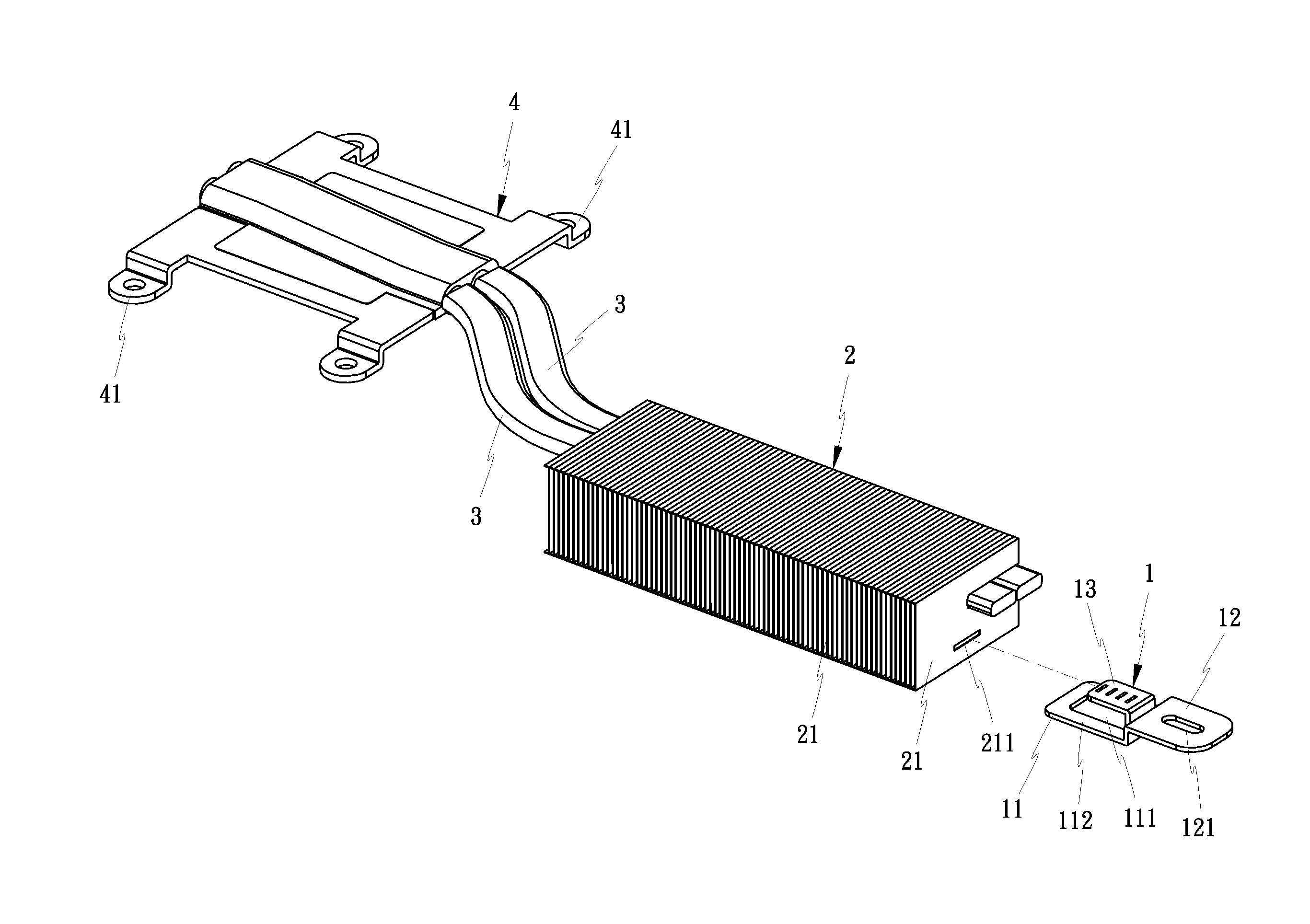
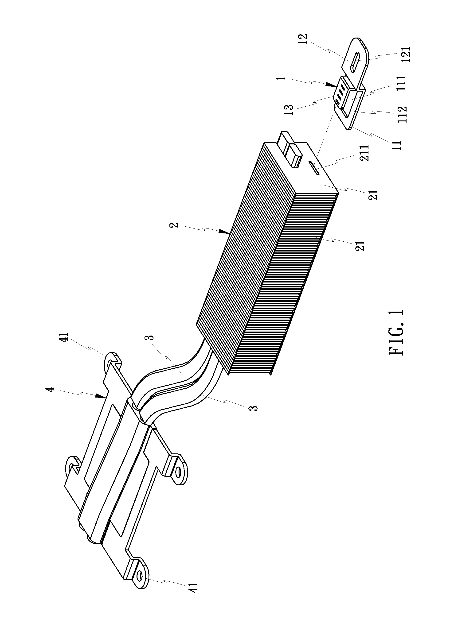
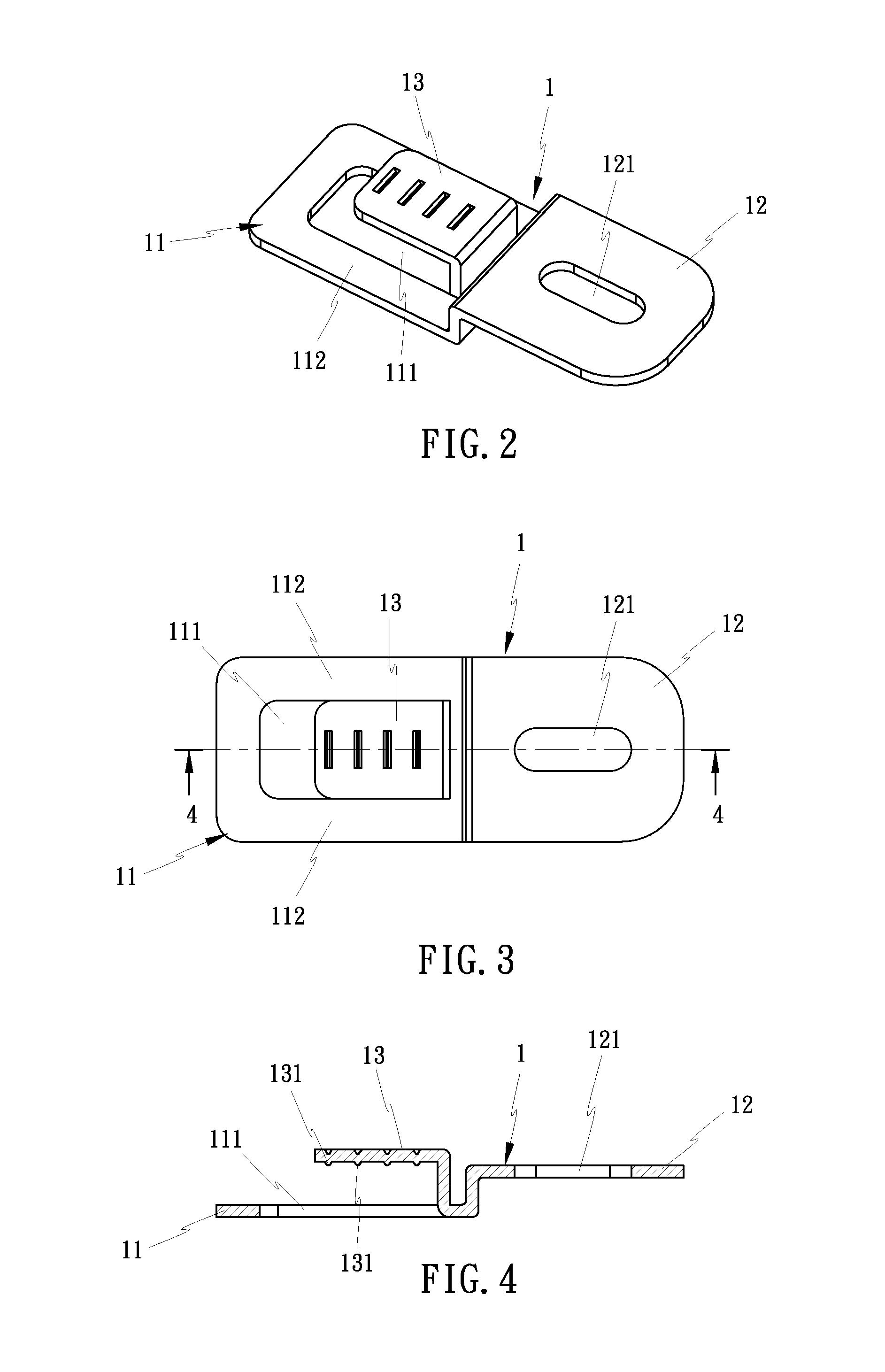
[0024]Referring to FIGS. 1 and 2, a heat sink and mounting bracket arrangement in accordance with the present invention is shown. The heat sink and mounting bracket arrangement comprises a radiation fin module 2, and a mounting bracket 1 connected to a rear end of the radiation fin module 2 in a tight fit manner. As illustrated in FIG. 3 and FIG. 4, the mounting bracket 1 is made from a metal plate sheet by stamping, comprising a bottom panel 11, an angled mounting panel 12 rearwardly extending from one end of the bottom panel 11, a mounting slot 121 cut through opposing top and bottom walls of the mounting panel 12, and an angled plug plate 13 forwardly extending from the bottom panel 11 adjacent to the angled mounting panel 12. Thus, the angled plug plate 13 extends in a direction opposite to the angled mounting panel 12. The radiation fin module 2 comprises a stack of radiation fins 21, and an insertion hole 211 located in one end of the stack of radiation fins 21. The angled plu...

second embodiment

[0029]In the present invention, as shown in FIG. 8 and FIG. 9, two rows of ribs 113 are located at the top wall 112 of the bottom panel 11 and symmetrically disposed at two opposite lateral sides relative to the opening 111. In each row, the ribs 113 are spaced from one another corresponding to the gaps in between the radiation fins 21. Thus, after insertion of the angled plug plate 13 into the insertion hole 211, the ribs 113 at the top wall 112 of the bottom panel 11 and the ribs 131 at the angled plug plate 13 are respectively engaged into the gaps in between the radiation fins 21, enhancing the connection tightness between the mounting bracket 1 and the radiation fin module 2 and effectively prohibiting separation between the mounting bracket 1 and the radiation fin module 2.

third embodiment

[0030]In the present invention, as shown in FIGS. 11-13, the bottom panel 11 and angled plug plate 13 of the mounting bracket 1 do not have the aforesaid ribs 113,131, however, the thickness of the angled plug plate 13 is slightly larger than the size of the insertion hole 211 of the radiation fin module 2. After insertion of the angled plug plate 13 into the insertion hole 211 of the radiation fin module 2 by force, the mounting bracket 1 and the radiation fin module 2 are tightly secured together (see FIG. 1).

[0031]The annexed drawings simply illustrate the technical features of the aforesaid three embodiments of the present invention. It is to be understood that various modifications and enhancements may be made without departing from the spirit and scope of the invention.

[0032]In conclusion, the invention provides a heat sink and mounting bracket arrangement, which comprises a radiation fin module 2, and a mounting bracket 1 press-fitted into and clamped on a rear end of the rad...


PUM


Abstract

A heat sink and mounting bracket arrangement includes a radiation fin module including a stack of radiation fins and an insertion hole located in one end of the stack of radiation fins, and a mounting bracket made from a metal plate sheet by stamping and including a bottom panel clamped on a bottom wall of the stack of radiation fins, an angled mounting panel rearwardly extending from one end of the bottom panel, a mounting slot cut through opposing top and bottom walls of the mounting panel for the mounting of a fastening member to affix the mounting bracket to an external substrate, and an angled plug plate forwardly extending from the bottom panel and tightly press-fitted into the insertion hole of the radiation fin module.

Description

BACKGROUND OF THE INVENTION[0001](a) Field of the Invention[0002]The present invention relates to heat sink technology, and more particularly to a heat sink and mounting bracket arrangement, which comprises a radiation fin module, and a mounting bracket press-fitted into the radiation fin module and clamped on the bottom wall of the radiation fin module for enabling the radiation fin module to be conveniently fastened to a substrate.[0003](b) Description of the Prior Art[0004]Conventional heat sinks generally comprise a heat sink base and a radiation fin module. Some heat sinks have heat pipes added thereto, and a heat transfer plate bonded to the heat pipes outside the radiation fin module and the heat sink base. In this design, each heat pipe has the hot end thereof directly or indirectly attached to the heat source, and the cold end thereof embedded to the heat sink base or inserted through the radiation fin module. Thus, the heat pipes can rapidly transfer waste heat from the he...

Claims


Application Information

Patent Timeline
IPC IPC(8): F28F3/02
CPCF28F3/02H05K1/0201H05K1/18H05K7/20336H05K7/20409H05K2201/10431H01L23/3672H01L23/4006H01L23/427H01L2924/0002F28F9/007F28D15/0233F28D15/0275F28F1/32H01L2924/00H01L23/4093
Inventor HUANG, TSUNG-HSIEN
Owner HUANG TSUNG HSIEN
Why Eureka
Try Eureka