
Control method and control device for inverter system

Active Publication Date: 2016-05-12
DELTA ELECTRONICS INC
View PDF7 Cites 11 Cited by
  • Summary
  • Abstract
  • Description
  • Claims
  • Application Information

AI Technical Summary

Benefits of technology

The technical solution allows multiple inverter units to share power effectively while maintaining good voltage accuracy. It also allows the output voltage to be adjusted to match another system's voltage, making it easier to connect systems and meet synchronization requirements.

Problems solved by technology

Therefore, it is not easy to fully achieve voltage regulation and power sharing objectives by simply setting the same voltage command for each inverter unit for voltage closed-loop control.
That is to say, voltage regulation and power sharing cannot be achieved simultaneously, and a compromise often needs to be made for the design of an inverter system.

Method used


Image

  • Control method and control device for inverter system
  • Control method and control device for inverter system
  • Control method and control device for inverter system

Examples


embodiment 1

[0104]In addition to the system voltage controller 100 and the unit voltage controller 200, the control device further comprises a pulse width modulation (PWM) unit 300. The voltage command signal e* generated by the unit voltage controller 200 is sent to the pulse width modulation unit 300 to generate switching signals reflecting the voltage command signal e*, and the switching signals are further used to control the switching elements (e.g., IGBT, Mosfet, etc.) of the inverter unit FIG. 11 is a schematic diagram of the structure of the control device.

embodiment 2

[0105]FIG. 12 is a schematic diagram of the structure of the control device.

[0106]In addition to the system voltage controller 100 and the unit voltage controller 200, the control device further comprises a voltage control module 400 and a pulse width modulation unit 300. The voltage control module 400 is used for receiving the voltage command signal e* and the feedback signal Vo reflecting the output voltage of the inverter unit, and further generating a second voltage command signal e′ for closed-loop control. The voltage control module 400 makes Vo follow e*. The pulse width modulation unit 300 is used for receiving the second voltage command signal e′ and generating switching signals for reflecting the second voltage command signal e′, and controlling the switching elements of the inverter unit based on the switching signals.

embodiment 3

[0107]FIG. 13 is a schematic diagram of the structure of the control device.

[0108]In addition to the system voltage controller 100 and the unit voltage controller 200, the control device further comprises a voltage control module 400, a pulse width modulation unit 300 and a signal superposition unit 500.

[0109]The voltage control module 400 is used for receiving the voltage command signal e* and the feedback signal Vo reflecting the output voltage of the inverter unit, and generating a second voltage command signal e′. The signal superposition unit 500 is used for receiving and superimposing the voltage command signal e* and the second voltage command signal e′, and generating a third voltage command signal e″. Thus, the voltage command signal e* applies a feed forward amount on e′, to make Vo vary faster as e* varies, which also make the dynamic response of the system more faster. The pulse width modulation unit 300 is used for receiving the third voltage command signal e″ and gener...


PUM


Abstract

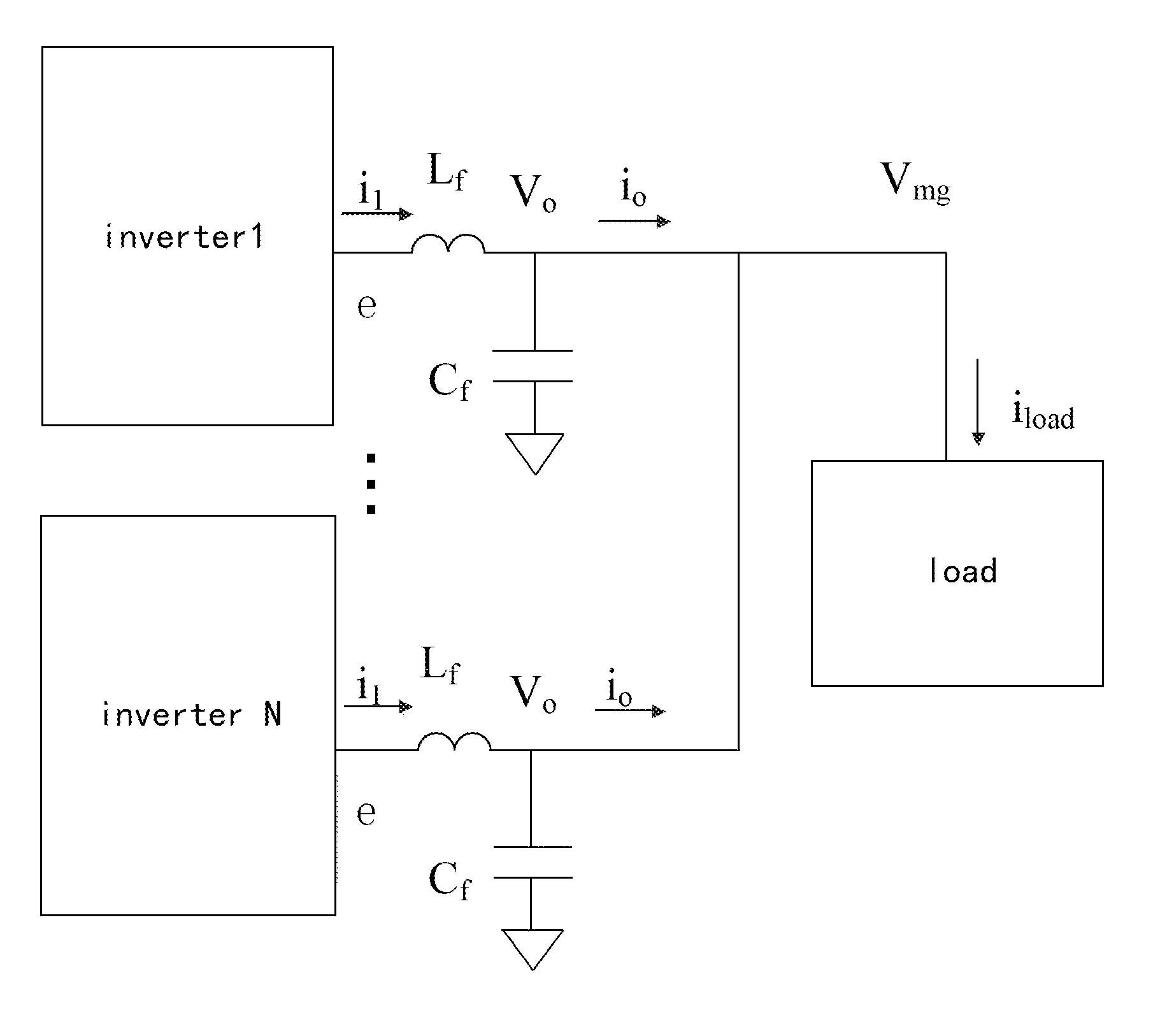
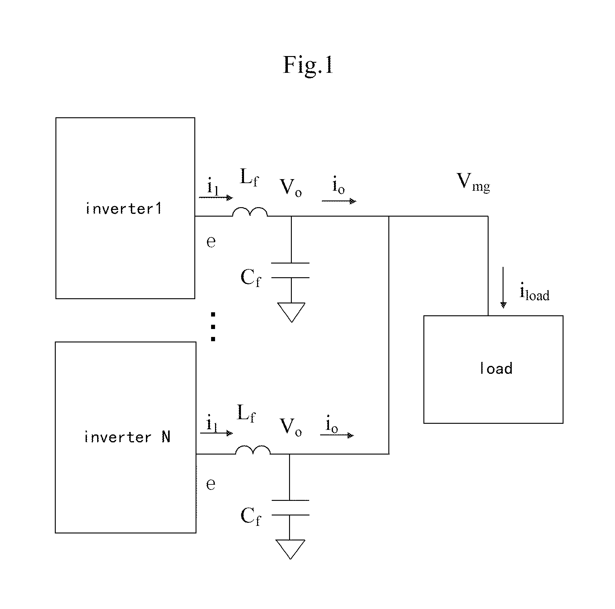
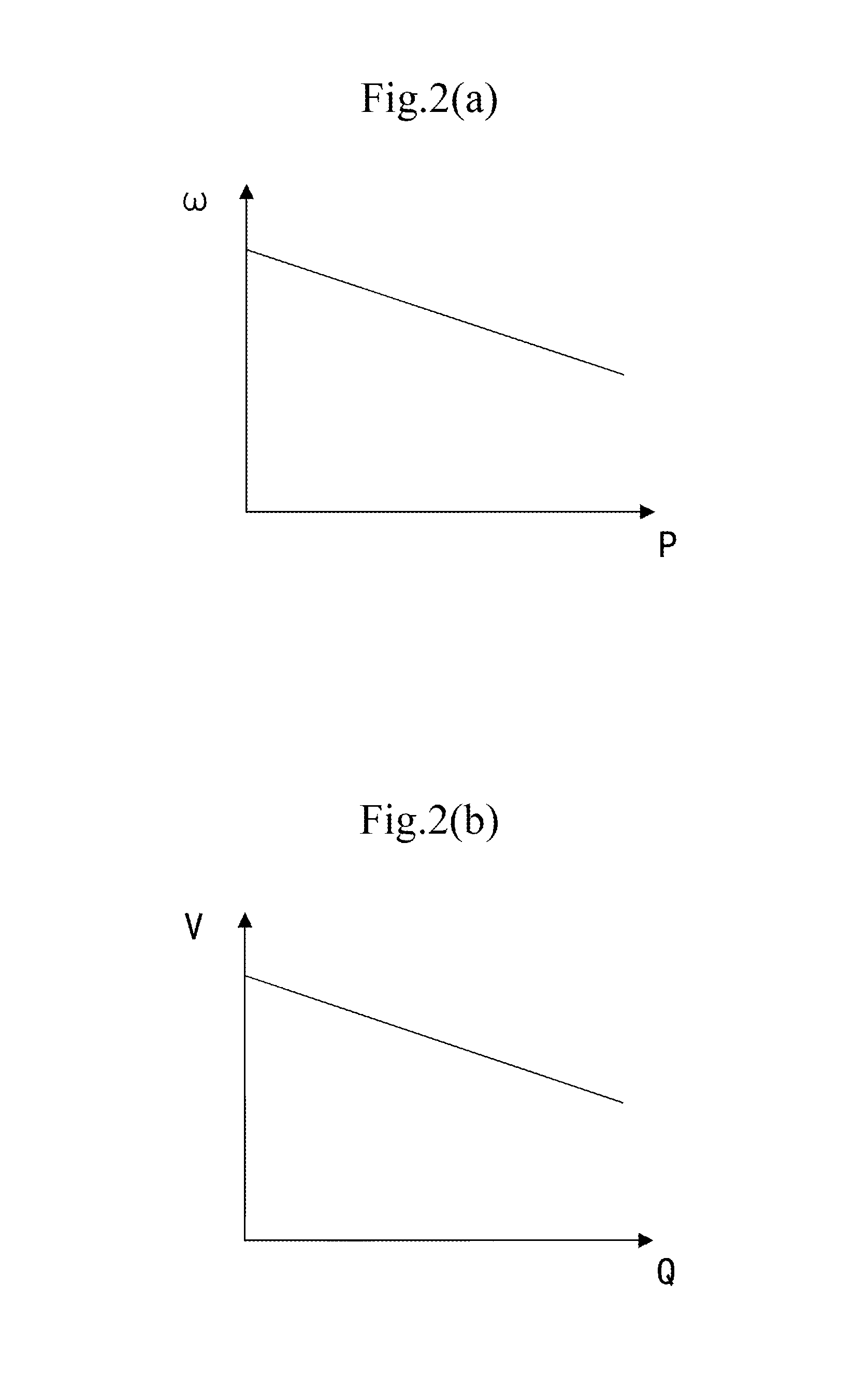
The present application discloses a control method and a control device for parallel inverters. The method comprises: receiving a feedback signal Vmg reflecting load voltage and a voltage reference signal Vref to generate a command signal Pset reflecting active power and a command signal Qset reflecting reactive power; taking the command signal Pset reflecting active power as the first offset of an active power-output voltage frequency curve (P-F) of an inverter unit, and taking the command signal Qset reflecting reactive power as the second offset of an reactive power-output voltage amplitude curve (Q-V) of the inverter unit; transversely translating the curve (P-F) of the inverter unit according to the first offset, transversely translating the curve (Q-V) of the inverter unit according to the second offset, and adjusting the load voltage of the inverter system by means of adjusted output voltage frequency and output voltage amplitude of the inverter unit.

Description

CROSS-REFERENCE TO RELATED APPLICATIONS[0001]This non-provisional application claims priority under 35 U.S.C. §119(a) on Patent Application No. 201410621150.4 filed in P.R. China on Nov. 6, 2014, the entire contents of which are hereby incorporated by reference.[0002]Some references, if any, which may include patents, patent applications and various publications, may be cited and discussed in the description of this invention. The citation and / or discussion of such references, if any, is provided merely to clarify the description of the present invention and is not an admission that any such reference is “prior art” to the invention described herein. All references listed, cited and / or discussed in this specification are incorporated herein by reference in their entireties and to the same extent as if each reference was individually incorporated by reference.FIELD OF THE PRESENT INVENTION[0003]The present application relates to an inverter system, and particularly to a control metho...

Claims


Application Information

Patent Timeline
IPC IPC(8): H02M7/44
CPCH02M7/44H02M7/493
Inventor LU, CHENGZHANG, JIAMINZHOU, JIANHONGWU, HONGYANG
Owner DELTA ELECTRONICS INC
Learn More