Method of connecting metal strips

a metal strip and metal strip technology, applied in metal-working equipment, metal-working equipment, manufacturing tools, etc., can solve problems such as negative effects on further processing

Inactive Publication Date: 2016-05-19
BWG BERGWERK & WALZWERK MASCHINENBAU GMBH
View PDF7 Cites 2 Cited by
  • Summary
  • Abstract
  • Description
  • Claims
  • Application Information

AI Technical Summary

Benefits of technology

[0008]It is therefore an object of the present invention

Problems solved by technology

The strip connection is particularly important, since defective s

Method used


Image

  • Method of connecting metal strips
  • Method of connecting metal strips
  • Method of connecting metal strips

Examples


first embodiment

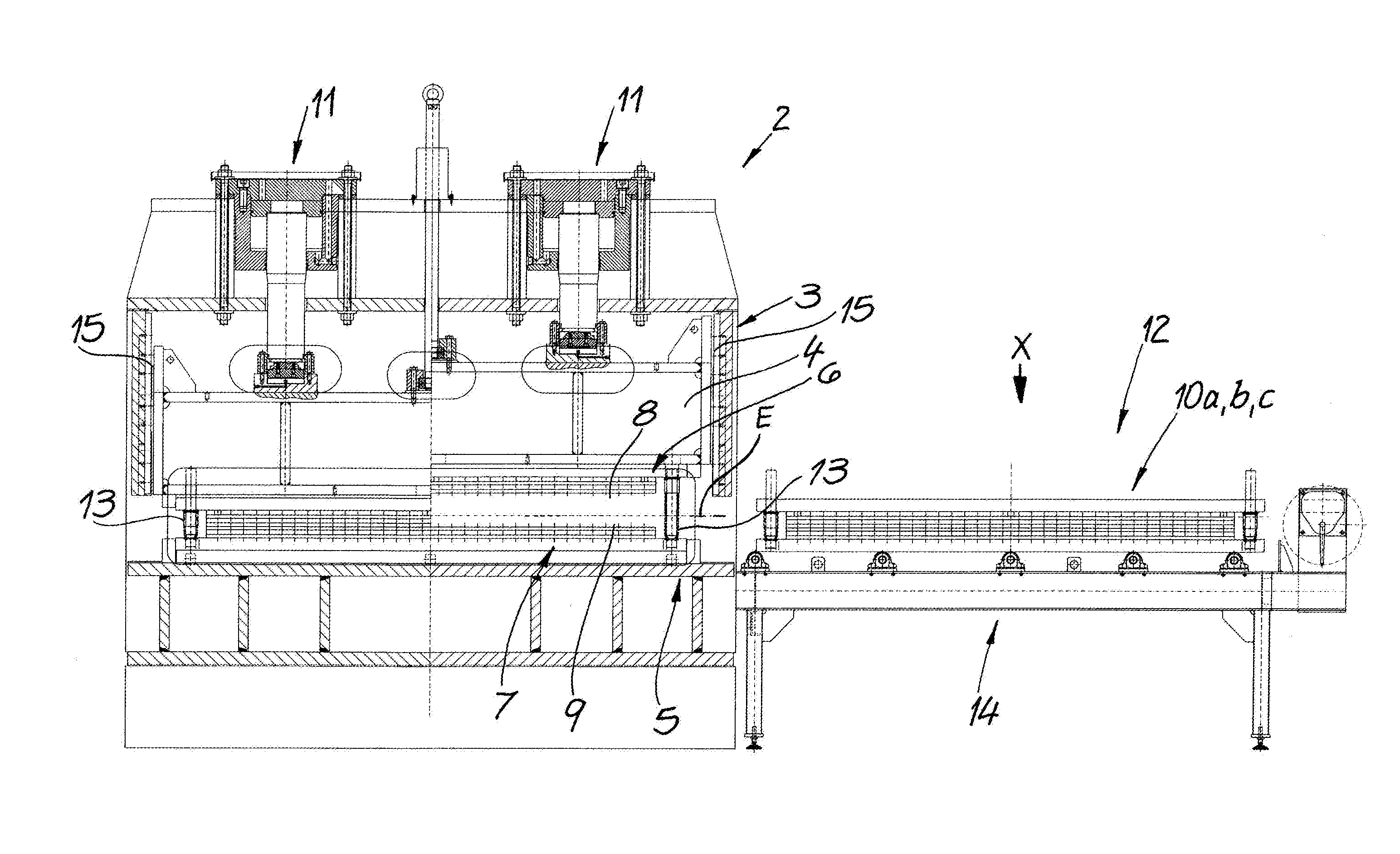
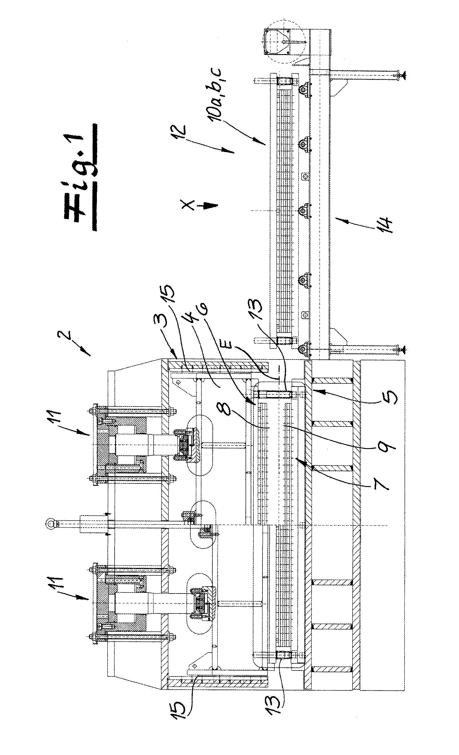
[0044]In FIGS. 1 and 2 a first embodiment is illustrated in which the tools 6, 7 are moved by the tool changer 12 transversely with respect to the strip-travel direction B out of the working position and into the waiting position. In this embodiment the tool changer 12 is laterally adjacent to the press 2 for this purpose. It has a change table 14 with a plurality of tool sets 10a, 10b, 10c one behind the other in the strip-travel direction B. If the tool located in the connection press 2 is to be replaced, it is pulled (or pushed) transversely with respect to the strip-travel direction B out of the press and onto the change table 14. The change table 14 then moves parallel to the strip-travel direction, for example by one position, so that then another tool can be pushed (or pulled) transversely with respect to the strip-travel direction B into the press 2. In the simplified plan view in FIG. 2 it can be seen that in the illustrated embodiment four different tools or tool sets 10a,...

second embodiment

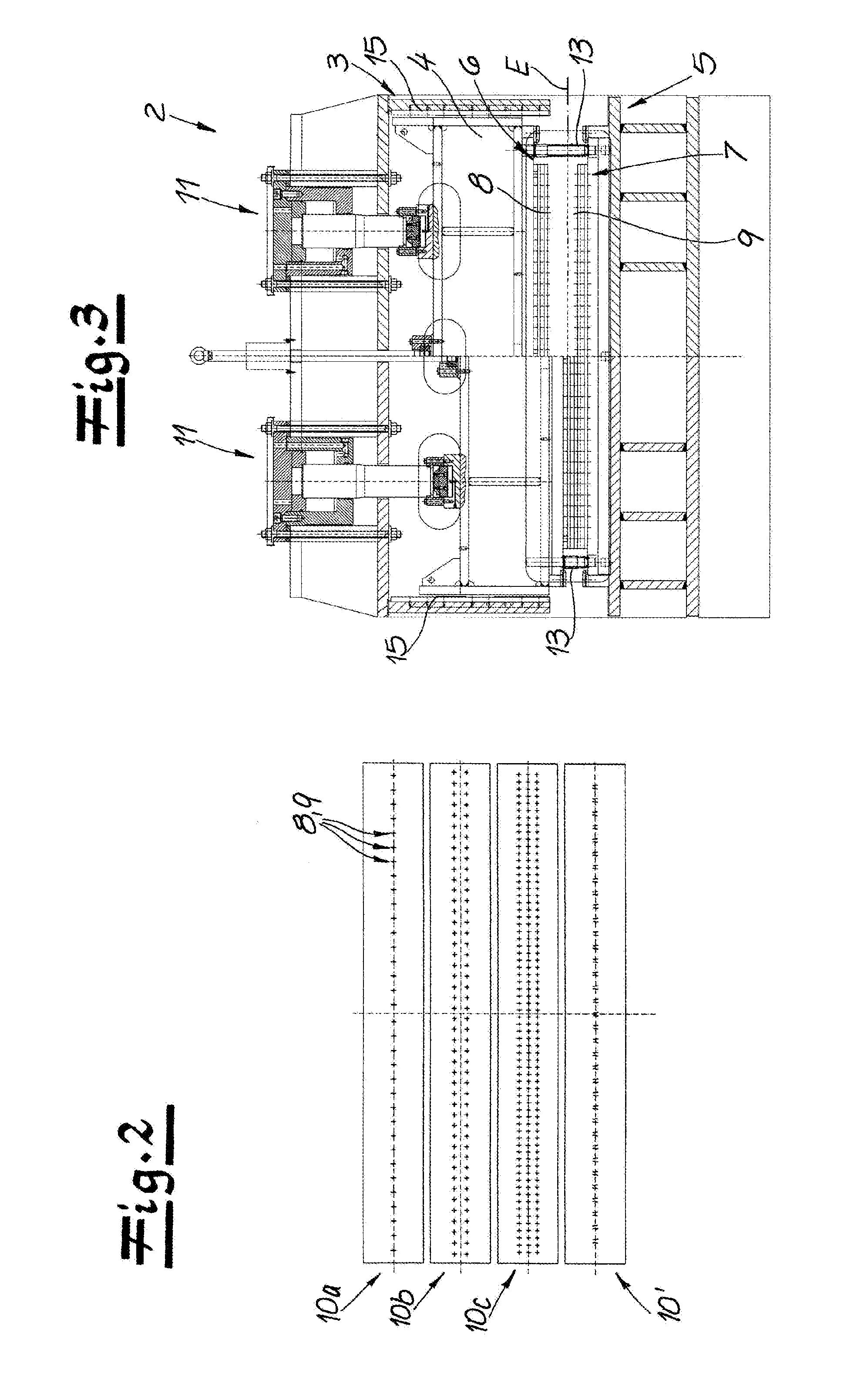
[0046]While the tool sets 10a, 10b, and 10c or 10 are changed transversely with respect to the strip-travel direction B in the embodiment according to FIGS. 1 and 2, FIGS. 3 to 5 show a second embodiment in which the tool sets 10a, 10b, and 10c or 10 are moved along the strip-travel direction B for changing purposes. The individual tool sets are in turn one behind the other in the strip-travel direction B; however, this time they are not laterally offset relative to the connection press 2, but are offset relative to the connection press 2 in the strip-travel direction. Nevertheless, travel of the metal strip is not disrupted, since the upper tools 6 are always above the metal strip or the strip plane E and the lower tools 7 are always below the metal strip, and since the guide posts 13 are always outside the strip region. In this embodiment the tool set can then also be changed when the strip is in the machine. FIG. 4 shows a view in which, for example, the punch tool 10 is in the m...


PUM

PropertyMeasurementUnit
Fractionaaaaaaaaaa
Fractionaaaaaaaaaa
Fractionaaaaaaaaaa

Abstract

A trailing end of a first metal strip is connected to a leading end of a second metal strip in a strip-treatment plant by first forming at least one of the strips as a cold-rolled, non-annealed metal strip and then superposing the trailing end of the first strip and the leading end of the second strip at an overlap. Then the strips are connected at the overlap at at least 20 connection points per meter of the strips by clinching without through cutting.

Description

FIELD OF THE INVENTION[0001]The present invention relates to method of connecting metal strips. More particularly this invention concerns strip-connecting method of a strip-treatment plant.BACKGROUND OF THE INVENTION[0002]In a strip-treatment plant it is frequently necessary to connect a trailing end of a first metal strip to the leading end of a second metal strip. To do this, the trailing and leading ends are positioned one above the other at an overlap and are connected to one another at the overlap at several connection points by clinching without separation and consequently without a cutting component.[0003]In strip-treatment plants that are also designated as strip-processing lines, strips wound into coils are generally unwound in the upstream intake end, then run through one or more treatment stations and at the outlet end are, if required, wound up again or alternatively are also cut into plates. The leading end of a new coil is connected to the trailing end of the preceding...

Claims


Application Information

Patent Timeline
IPC IPC(8): B21D39/03
CPCB21D39/031B21D39/00B21C47/247B21D39/03
Inventor NOE, ANDREASHOFFMANN, JENSAMBAUM, FRIEDHELM
Owner BWG BERGWERK & WALZWERK MASCHINENBAU GMBH
Why Eureka
Try Eureka