Injector head chain synchronization device

a technology of synchronization device and injector head, which is applied in the direction of drilling rods, drilling pipes, borehole/well accessories, etc., can solve the problems of large internal forces within the system, wear and possible wear and fatigue of continuous tubing,

Active Publication Date: 2016-05-19
STIMLINE
View PDF3 Cites 15 Cited by
  • Summary
  • Abstract
  • Description
  • Claims
  • Application Information

AI Technical Summary

Benefits of technology

[0035]FIG. 7a-7d shows a principle drawing of the running of the injector head according to another embodiment of the invention where there are arranged separate regulators on each side of the skates which have the purpose of maintaining the same position between the skate and move the skate in the horizontal direction.

Problems solved by technology

This will lead to wear and possible fatigue of the continuous tubing because one the first chain blocks on the first chain will engage with the continuous tubing prior to second chain blocks on the second chain.
This synchronizing of the chain could cause wear and fatigue of the continuous tubing and loss of the lifting force.
This leads to large internal forces within the system due to loss of friction between the chain blocks and the continuous tubing.
The chain blocks could slip when they are in contact with the continuous tubing and this could cause damage to the continuous tubing.
This will lead to wear and possible fatigue of the continuous tubing because the first chain blocks on the first chain will engage with the continuous tubing prior to second chain blocks on the second chain.

Method used


Image

  • Injector head chain synchronization device
  • Injector head chain synchronization device
  • Injector head chain synchronization device

Examples


Embodiment Construction

[0039]The following describes preferred embodiments of the conveyor apparatus of the present invention and which is exemplary for the sake of understanding the invention and non-limiting.

[0040]In the present context, the term “injector head” is to be construed as being synonymous with the term conveyor apparatus as defined in the claims.

[0041]Further, the term “counter-force member” is synonymous with the term “skate” frequently used in the art.

[0042]All throughout the specification including the claims, the words “continuous tubing”, “skate”, “belt drive chain”, “actuator”, “coiled tubing”, “borehole”, “wellhead”, “lubricator strings”, “bearing”, “BOP”, “injector head”, “sensor”, “control system”, “roller” are to be interpreted in the broadest sense of the respective terms and includes all similar items in the field, known by other terms, as may be clear to persons skilled in the art.

[0043]Restriction / limitation, if any, referred to in the specification, is solely by way of example...


PUM


Abstract

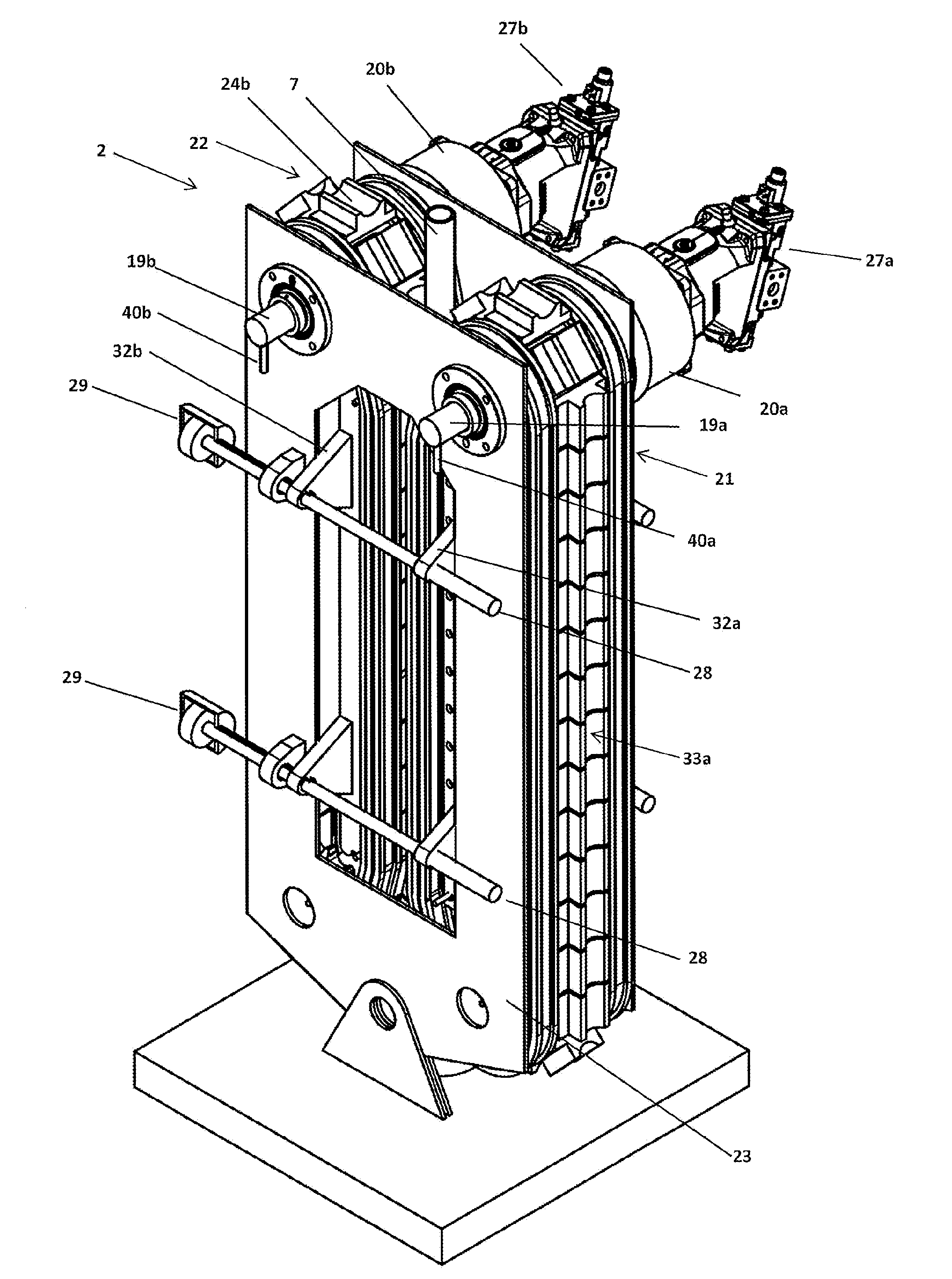
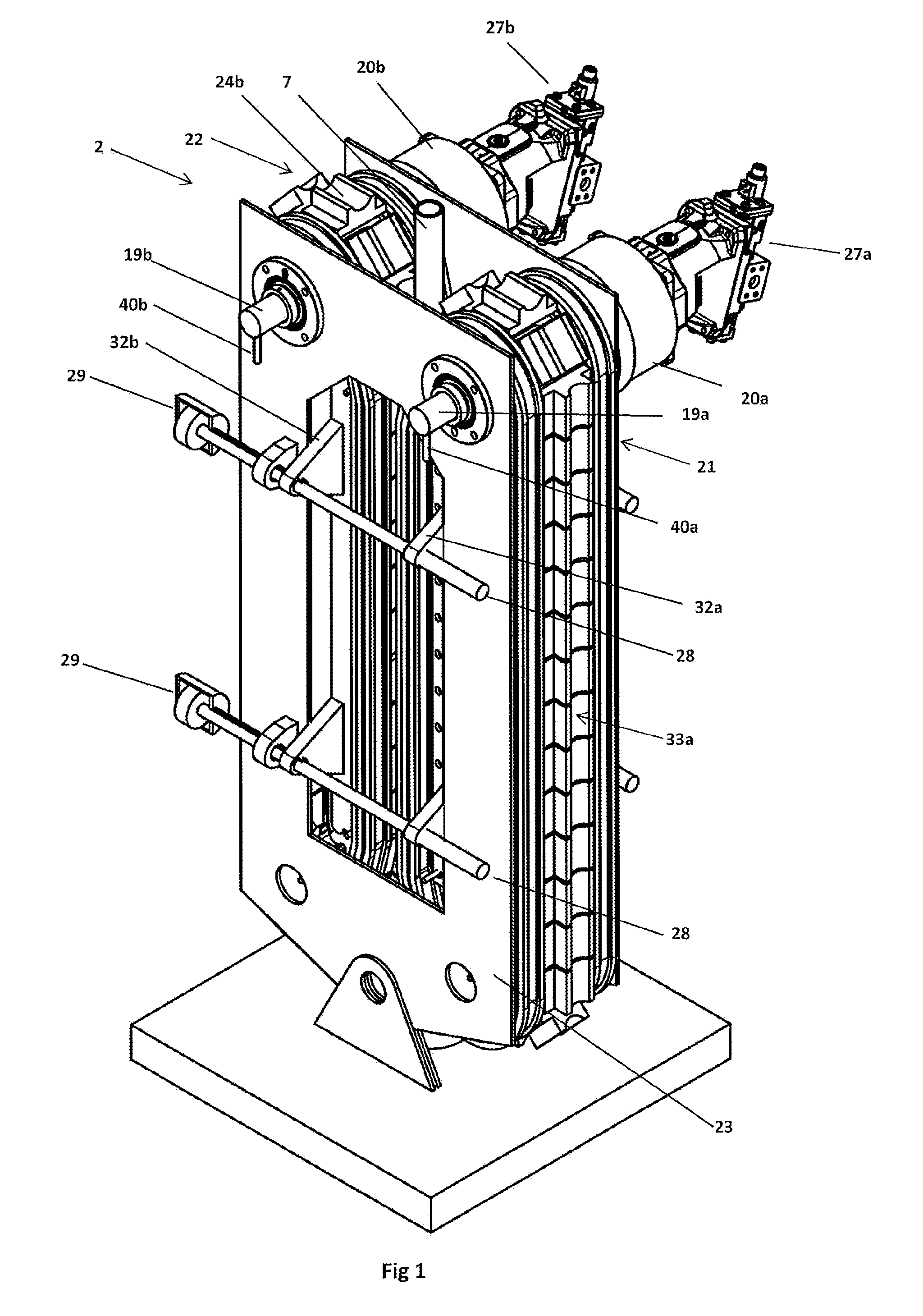
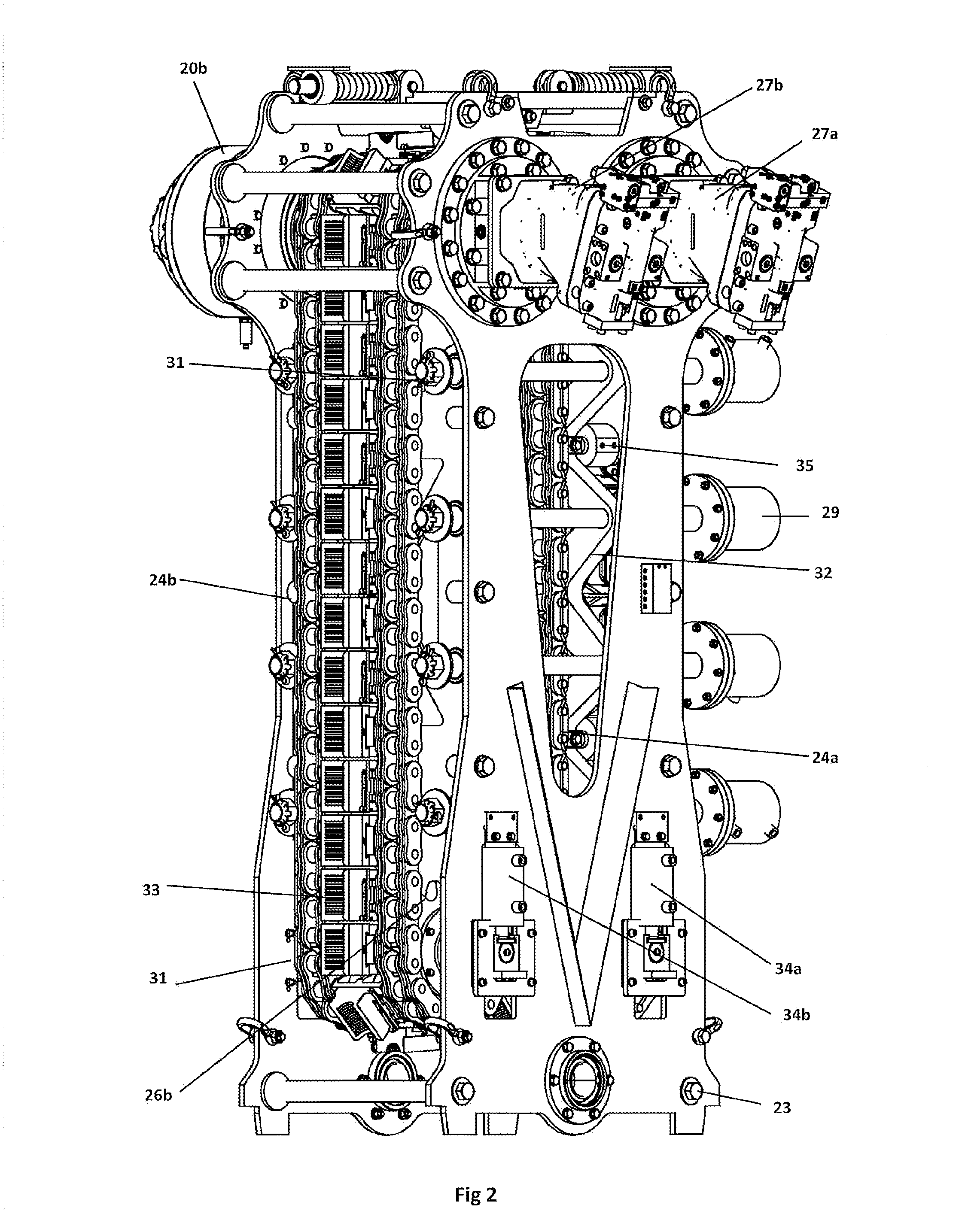
The invention relates to an injector head (2) comprising; a pair of oppositely located, cooperatively movable, segmented continuous belt drive chains (21; 22), said each belt drive chain (21, 22) running over a respective pair of drive sprockets (25a, 25b) and tension sprockets (26a, 26b), wherein a tubing receiving section (7′) is defined between the belt drive chains (21, 22). The tubing receiving section (7′) having a tubing section centerline (46) extending through the center of the tubing receiving section (7′). The injector head (2) having an injector centerline (45) extending through the centerline of the injector head (2), said injector centerline (45) and said tubing section centerline (46) being substantially aligned in the longitudinal direction in an initial position, a pair of elongate counter-force members (32a, 32b) is positioned at each side of the tubing receiving section (7′). The injector head (2) has at least one actuator (35) adapted to move at least one of said elongate counter-force elongate member (32a, 32b) in order to bring the tubing section centerline (46) out of alignment with said injector centerline (45).

Description

FIELD OF THE INVENTION[0001]The present invention relates to a conveyor apparatus or injector head to enable feeding of continuous elongate device (CED), such as e.g. coiled tubing, rod, wire or wireline down through the conveyor apparatus, to enable insertion of tools through the wellhead and into a well below, or up through the conveyor apparatus by pulling action enabling retrieval of such tools from the wellhead and the well below. In particular the invention relates to an injector head with synchronized belt drive chains.[0002]Such a conveyor apparatus is frequently called an “injector head” in this particular field of use[0003]The wellhead is primarily used for oil and natural gas exploration and production operations.[0004]Particularly, the present invention relates to a technology for inserting and retrieval of a drill tool being supported by continuous elongate device (CED) in a non-limiting example being e.g. a continuous tubing, suitably coiled tubing running through the ...

Claims


Application Information

Patent Timeline
Patent Type & Authority Applications(United States)
IPC IPC(8): E21B19/08E21B19/22
CPCE21B19/22E21B19/08E21B19/084
Inventor BJORNENAK, MADS
Owner STIMLINE
Why Eureka
Try Eureka