Hose and Tubing Connector Device, Assembly and Method of Assembly

a technology of connectors and hoses, applied in the direction of hose connections, valve housings, drawing-off water installations, etc., can solve the problems of time-consuming, labor-intensive, unsafe, etc., and achieve the effect of strong connection of assembly, and preventing mal-forming of sealing or crimping areas

a technology of connectors and hoses, applied in the direction of hose connections, valve housings, drawing-off water installations, etc., can solve the problems of time-consuming, labor-intensive, unsafe, etc., and achieve the effect of strong connection of assembly, and preventing mal-forming of sealing or crimping areas

US20160138738A1Inactive Publication Date: 2016-05-19QUICK FITTING

Image

  • Hose and Tubing Connector Device, Assembly and Method of Assembly
  • Hose and Tubing Connector Device, Assembly and Method of Assembly
  • Hose and Tubing Connector Device, Assembly and Method of Assembly

Examples


Embodiment Construction

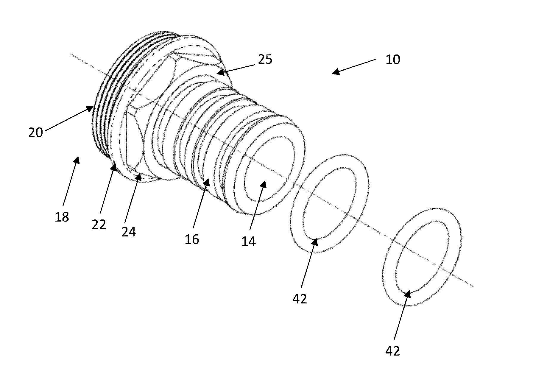
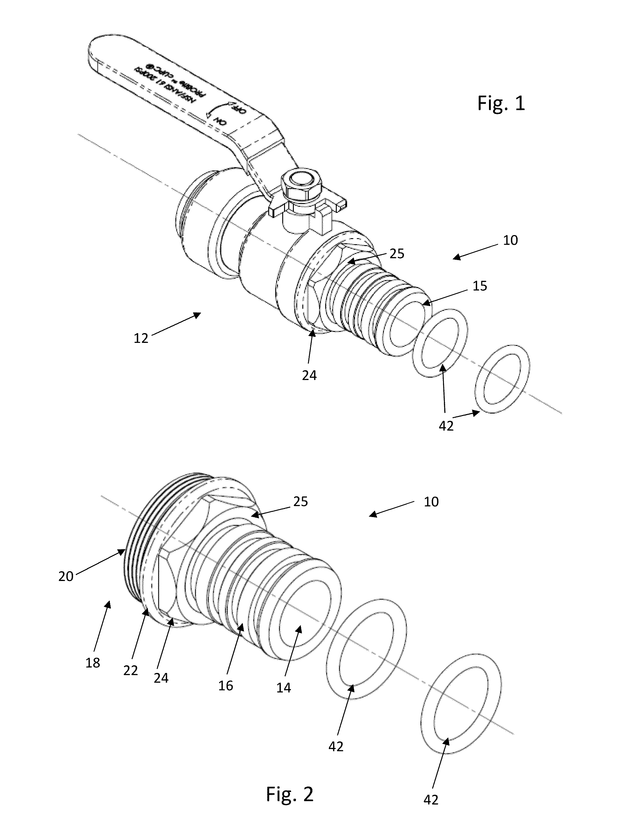
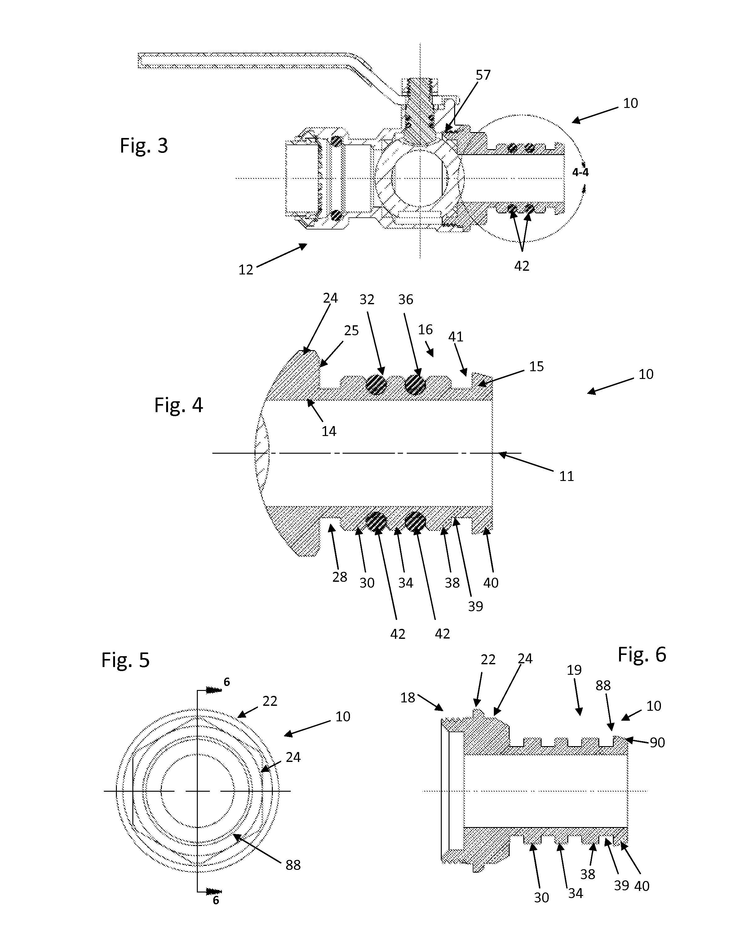
[0032]As shown in FIGS. 1 and 2, the present invention can be provided in various embodiments and with various components, including an adapter 10 which can be mated with a fitting 12 (e.g., the ball valve fitting shown at 12). The adapter 10 shown in FIGS. 1 through 6 is substantially tubular and / or cylindrical with an inner wall 14, an outer wall 16, a first axial end 18 with a threaded exterior 20 and a second axial end 19 with ledges 30, 34, 38, 40. The adapter further includes a rim 22 and a hexagonal or other similarly shaped annular edge 24 to assist, for example, in tightening and loosening the adapter 10 as it is secured to or removed from the fitting 12 in various embodiments. It will be appreciated that, while the adapter member 10 is shown with an axial end 18 having a threaded exterior 20 for a compression-type fitting connection, the adapter member 10 can also be provided with an axial end having a push-to-connect arrangement, such as may be described, for example, in ...


PUM

PropertyMeasurementUnit
tensile separation forcesaaaaaaaaaa
radial distanceaaaaaaaaaa
pressureaaaaaaaaaa

Abstract

A piping hose connector adapter can be employed as a stand-alone connector or integrated into a valve or fitting. The adapter can comprise a substantially cylindrical body having inner and outer walls, with a plurality of ledges extending radially outwardly from the outer wall and forming grooves therebetween. O-ring members can be inserted in one or more of the grooves. The adapter can be secured at one end to a fitting, and at the other end to a hose using a pressure applying device that can malform the hose around the outer surface of the adapter so as to compress the o-ring member.

Description

FIELD OF THE INVENTION[0001]The present invention provides methods, connection devices as well as tooling designs for the permanent connection of flexible and rigid tubing with one or more fittings. In various embodiments, the tubing can be steel, brass, stainless steel or copper corrugated flexible or rigid tubing.BACKGROUND AND SUMMARY OF THE INVENTION[0002]Piping systems exist to facilitate the flow of fluids (e.g., liquid, steam, gas (such as air) or plasma). For example, homes, schools, medical facilities, commercial buildings and other occupied structures generally require integrated piping systems so that water and / or other fluids can be circulated for a variety of uses. Liquids and / or gases such as cold and hot water, breathable air, glycol, compressed air, inert gases, cleaning chemicals, waste water, plant cooling water and paint and coatings are just some examples of the types of fluids and gases that can be deployed through piping systems. Tubing and piping types can inc...

Claims


Application Information

Patent Timeline
19 May 2016
Publication
US20160138738A1
IPC
F16L17/06
CPC
F16L17/06; B21D39/048; F16K5/0642; F16K27/067; F16L13/143; F16L33/30; F16L37/0915
Inventors
CROMPTON, DAVID B.; DIAS, LIBARDO OCHOA