Light Strip and Method for Making a Light Strip

a technology of light strips and light strips, applied in the field of light strips, can solve the problems of increasing the complexity of the installation, generating more heat, and generating more heat, and achieve the effect of preventing heat dissipation and facilitating manufacture and assembly

Active Publication Date: 2016-05-19
MAG LED INC
View PDF2 Cites 24 Cited by
  • Summary
  • Abstract
  • Description
  • Claims
  • Application Information

AI Technical Summary

Benefits of technology

[0013]By employing apparatus and methods of the foregoing type an improved lighting strip is achieved using techniques that ease manufacture and assembly. In a disclosed embodiment a transparent sleeve is extruded around a pair of conductors that supply power to the lighting strip. The flexible printed circuit board carrying the LEDs is spaced from these supply conductors and are not overheated by them. In this embodiment a flexible circuit board has a number of separate strings of LEDs whose current is limited either by a resistor or a depletion mode field effect transistor. Each string of LEDs on the flexible circuit board has its own dedicated pair of solder pads that are each connected to one end of a jumper whose other end connects to one of the supply conductors.
[0014]These disclosed jumpers may be soldered in place in advance, so that the flexible circuit board and supply conductors are simultaneously coextruded into a flexible sleeve, with extrudate partially enveloping the jumpers. The printed circuit board is not enveloped by the extrudate to avoid trapping it in an insulating layer that prevents heat dissipation.
[0015]In some cases the flexible sleeve can be extruded around just the supply conductors and part of the jumpers, which jumpers to or connected to the supply conductors but not to the missing flexible circuit board. In that case the sleeve will have a longitudinal slit (a split). The split in can be opened with an appropriate tool that allows an end of the flexible circuit board to be inserted into this sleeve. Thereafter the tool is slid back to open progressive positions in the longitudinal split, allowing the rest of the flexible strip to be placed inside the sleeve. Thereafter, an assembler can solder the free ends of the jumpers to the solder pads on the flexible circuit board.

Problems solved by technology

Light emitting diodes have relatively small forward voltage drops and therefor require a voltage conversion unit such as a transformer, which adds to the complexity of the installation.
Also known light strips have included ASICs to regulate the applied voltage, but these ASICs tend to be large, generate much heat, and have a tendency to pull off the underlying, flexible printed circuit board.
When the strip is relatively long, the buses must carry significant current that tends to heat a flexible circuit board and degrades the performance of the adjacent LEDs, possibly causing them to fail.
Such a common bus carries even more current, and generates even more heat that seriously affects the lighting elements.
Also, it can be difficult to mount in a single sleeve, long lighting strips or a number of serially connected lighting strips.

Method used


Image

  • Light Strip and Method for Making a Light Strip
  • Light Strip and Method for Making a Light Strip
  • Light Strip and Method for Making a Light Strip

Examples


Embodiment Construction

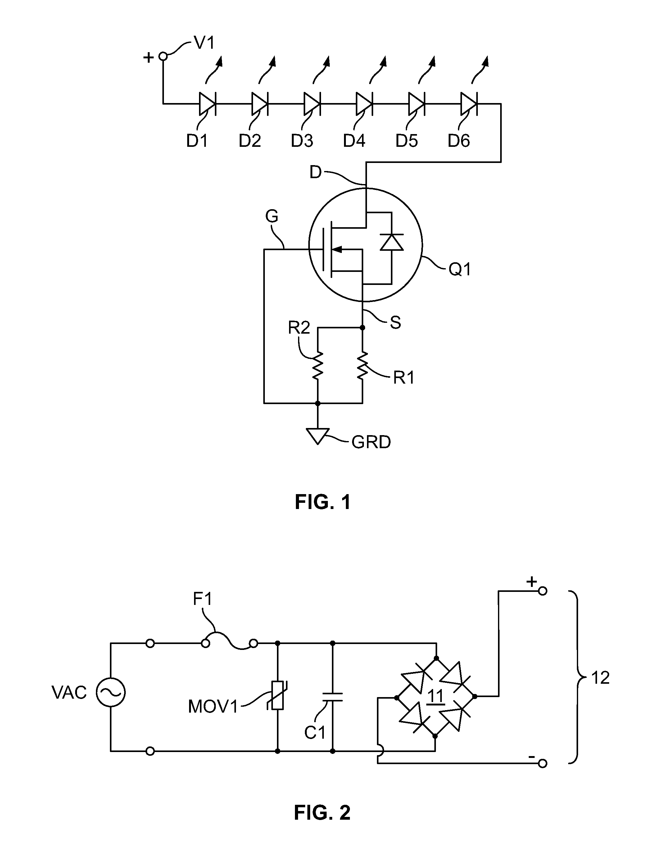
[0034]Referring to FIG. 1, the illustrated light circuit has six serially connected LEDs, D1, D2, D3, D4, D5, and D6, in that order (hereinafter LEDs D1-D6). LEDs D1-D6 are connected cathode to anode and are all connected to be forwardly biased by a positive potential at terminal V1. The anode of diode D1 is directly connected to terminal V1, while the cathode of diode D6 is directly connected to drain D of depletion mode field effect transistor Q1 (FET transistor Q1). In one embodiment transistor Q1 was a model CPC3708 transistor supplied by IXYS, Integrated Circuits Division, although other types of transistors from other suppliers may be used in other embodiments. Gate G of transistor Q1 is grounded, and its source S is connected through a parallel pair of resistors R1 and R2 to ground. Accordingly, the power input to this light circuit is applied across terminal V1 and ground.

[0035]Configured in this manner, transistor Q1 will conduct when relatively small voltage is applied acr...


PUM

PropertyMeasurementUnit
peak voltageaaaaaaaaaa
forward voltage dropaaaaaaaaaa
net resistanceaaaaaaaaaa

Abstract

A light strip has a flexible enclosure extruded around a pair of conductors. The enclosure contains a lighting assembly with one or more flexible substrates that are each populated with a plurality of light circuits. The substrates are spaced from the pair of conductors. The lighting assembly has a plurality of connecting devices for electrically coupling the lighting assembly to the pair of conductors

Description

CROSS-REFERENCES TO RELATED APPLICATIONS[0001]This application is a continuation of U.S. patent application Ser. No. 14 / 726,764, filed on Jun. 1, 2015, which claims the benefit of United States[0002]Provisional Patent Application, Ser. No. 62 / 006,382, filed Jun. 2, 2014, the contents of both being hereby incorporated by reference herein.BACKGROUND OF THE INVENTION[0003]1. Field of the Invention[0004]The present invention relates to lighting strips and methods for making the same, and in particular to extrusions and extrusion methods for such light strips.[0005]2. Description of Related Art[0006]Flexible printed circuit boards have been manufactured in strips that are populated with light emitting diodes. The strips can be mounted in a transparent tubular sleeve that is easily mounted in a variety of locations. These lighting strips can be placed inside cabinets, along corridors to light a walkway, or any place where a compact lighting source is required.[0007]Light emitting diodes h...

Claims


Application Information

Patent Timeline
Patent Type & Authority Applications(United States)
IPC IPC(8): F21S4/22F21K99/00F21V23/06F21V23/00F21V23/02H05B44/00
CPCF21S4/22F21V23/002F21V23/02F21Y2103/003F21K9/90F21Y2101/02F21V23/06F21Y2103/10F21Y2115/10H05K1/189H05K2201/10106H05B45/395Y02B20/30H05B45/40H05K1/00F21V19/0025
Inventor GREENE, JASON
Owner MAG LED INC
Why Eureka
Try Eureka