Solar thermal collector and building accessory structure
- Summary
- Abstract
- Description
- Claims
- Application Information
AI Technical Summary
Benefits of technology
Problems solved by technology
Method used
Image
Examples
Embodiment Construction
[0038]It is to be understood that the foregoing and other technical contents, features, and advantages are intended to be described more comprehensively by providing embodiments accompanied with figures hereinafter. In the following embodiments, wording used to indicate directions, such as “up,”“down,”“front,”“back,”“left,” and “right,” merely refers to directions in the accompanying figures. Therefore, the directional wording is used to illustrate rather than limit the invention. Moreover, the same or similar reference numerals represent the same or similar elements in the following embodiments.
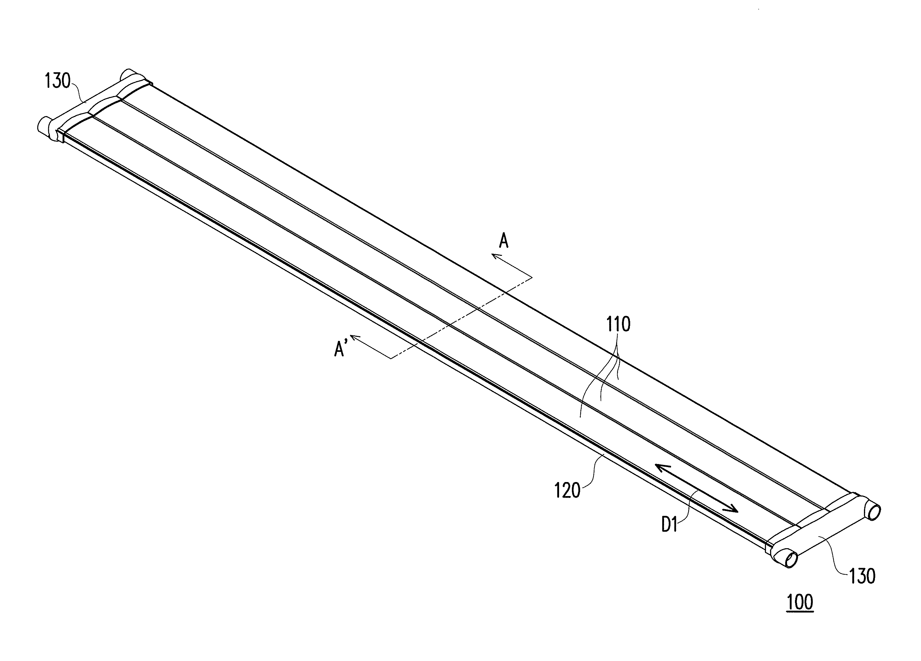
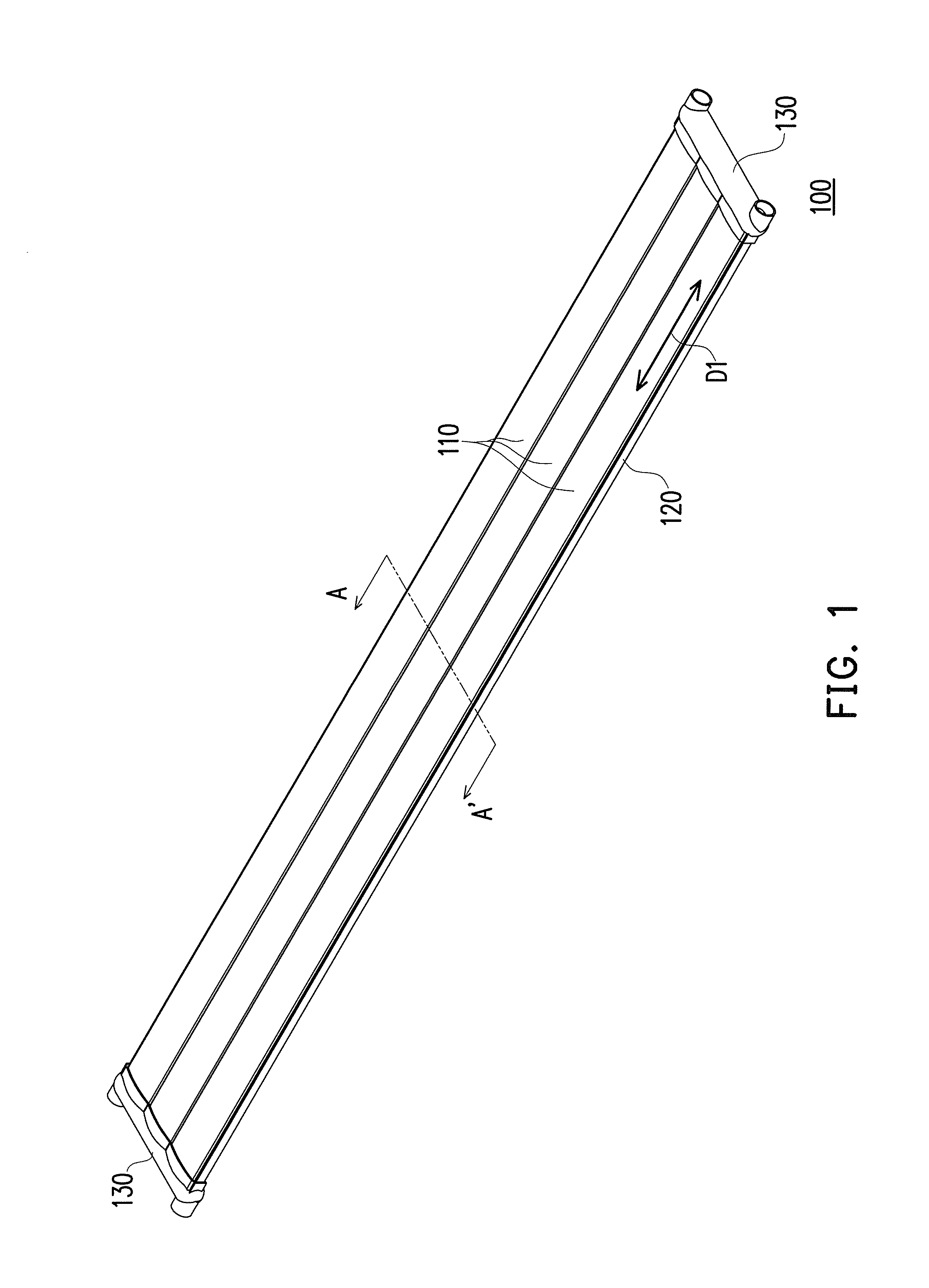
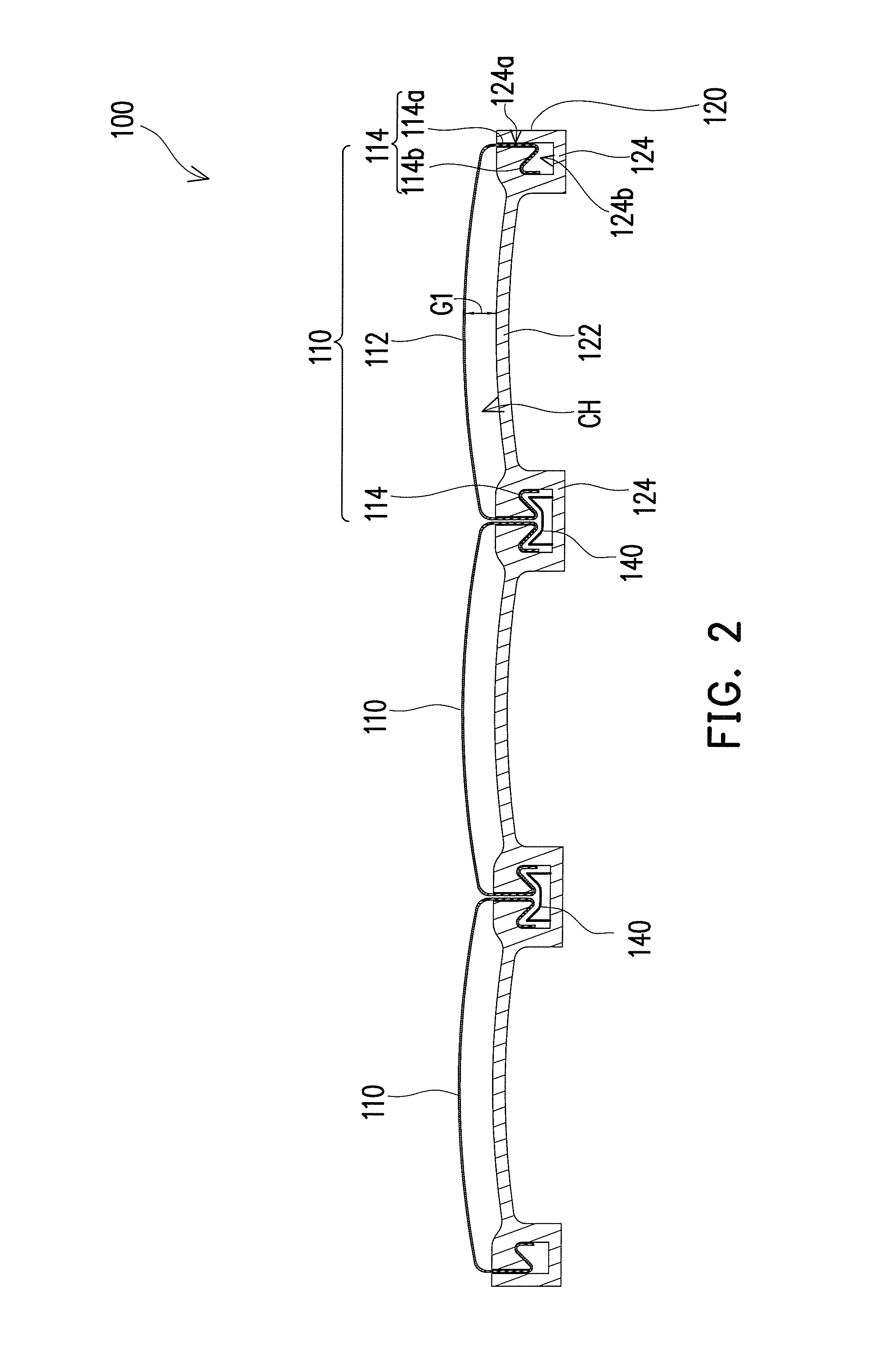
[0039]FIG. 1 is a schematic view of a solar thermal collector according to an embodiment of the invention. FIG. 2 is a schematic cross-sectional view of the solar thermal collector of FIG. 1 along the line A-A′. With reference to FIG. 1 and FIG. 2, in this embodiment, a solar thermal collector 100 includes at least one heat absorbing plate 110 and at least one heat insulating plate 120. The ...
PUM
| Property | Measurement | Unit |
|---|---|---|
| Time | aaaaa | aaaaa |
| Electrical conductivity | aaaaa | aaaaa |
| Area | aaaaa | aaaaa |
Abstract
Description
Claims
Application Information
 - R&D
- Intellectual Property
- Life Sciences
- Materials
- Tech Scout
- Unparalleled Data Quality
- Higher Quality Content
- 60% Fewer Hallucinations
Browse by: Latest US Patents, China's latest patents, Technical Efficacy Thesaurus, Application Domain, Technology Topic, Popular Technical Reports.
© 2025 PatSnap. All rights reserved.Legal|Privacy policy|Modern Slavery Act Transparency Statement|Sitemap|About US| Contact US: help@patsnap.com


