Double wall self-contained liner

a self-contained liner and double-walled technology, applied in the direction of machines/engines, mechanical equipment, cylinders, etc., can solve the problems of reducing the overall affecting the engine, and requiring even more complex sculptural work. , to achieve the effect of reducing the total package size, cost and weight of the engine, and reducing the dead weigh

Inactive Publication Date: 2016-09-22
FEDERAL MOGUL MOTORPARTS LLC
View PDF6 Cites 1 Cited by
  • Summary
  • Abstract
  • Description
  • Claims
  • Application Information

AI Technical Summary

Benefits of technology

[0008]The engine assembly can be used in both gasoline and diesel applications and is capable of achieving numerous advantages over the previously developed designs. The engine assembly is designed so that there is no need for the complex sculptured walls or complex engine block architecture for support or coolant distribution. In fact, the engine block and cooling jacket can be eliminated altogether, as the double-wall cylinder liner can provide the desired cooling path and carry all the clamping and thrust forces. Thus, the total package size, cost, and weight of the engine are reduced. The engine could alternatively be designed with “open block” architecture to reduce dead weight. For example, the assembly can be designed with a simple open block formed of aluminum, without loss of rigidity, as the cylinder liner can be self-supporting as far as pressure loads and stresses.
[0009]In addition, the double-wall cylinder liner can be clamped in position between the cylinder head and crankcase without any fastening features extending into the walls of the liner. Instead, tie rods can extend between the cylinder head and crankcase along the outer wall of the cylinder liner. Alternatively, the tie rods can connect the cylinder head and main bearing cradle. This feature is particularly beneficial when the cylinder liner is formed of aluminum, for example an aluminum cylinder liner designed for a diesel engine with high peak firing pressures.
[0010]The double-wall construction also provides a greater section modulus and thus more rigid structure for the same load carrying capability. The rigid structure leads to less deformation of the cylinder liner under assembly loads, and thus better oil control, which reduces lubricant oil consumption. The double-wall design also has an inherently greater damping capability than a single-wall liner. The greater damping capability means less vibration at the low frequency spectrum and thus a lower noise footprint.
[0011]The manifold and outer wall of the cylinder liner can also be designed with a plurality of fluid ports to control swirling of coolant flow and further improve heat transfer. In addition, the manifold can be designed with a simple low hydraulic loss channel to direct the coolant to or from the cooling chamber. Either bottom-up or top-down (reverse) coolant flows can be implemented. For example, the reverse coolant flow is oftentimes desired in conjunction with highly thermally loaded power units, as it inherently provides for more efficient heat transfer. The low hydraulic loss provides the opportunity for adiabatic applications related to the use of high temperature coolants, such as a sodium-potassium (NaK) alloy or silicon-based coolant formulation, which may prove convenient with combined heat and power concepts. The manifold can also be cast integral with the crankcase, and the need for complex gasket geometries to seal the cylinder liner can be minimized or eliminated. Improved heat transfer without cavitation can also be achieved due to the proximity and stream flow velocity of the coolant.

Problems solved by technology

However, smaller diesel engines shed greater amounts of heat than typical diesel engines.
This amount of lost heat requires even more complex sculpturing of the internal walls of the engine block to convey coolant to the diverse parts of the cylinder liner disposed in the engine block at the appropriate rate.
In addition to the high cost, the complex wall geometry creates stagnation of pockets of fluid, which induces problems with nucleate boiling and cavitation and can be harmful to the engine.
However, all of these expedients impose increased parasitic pumping losses, which are reflected in an undesirable increase in fuel consumption and carbon dioxide emissions.

Method used


Image

  • Double wall self-contained liner
  • Double wall self-contained liner
  • Double wall self-contained liner

Examples


Embodiment Construction

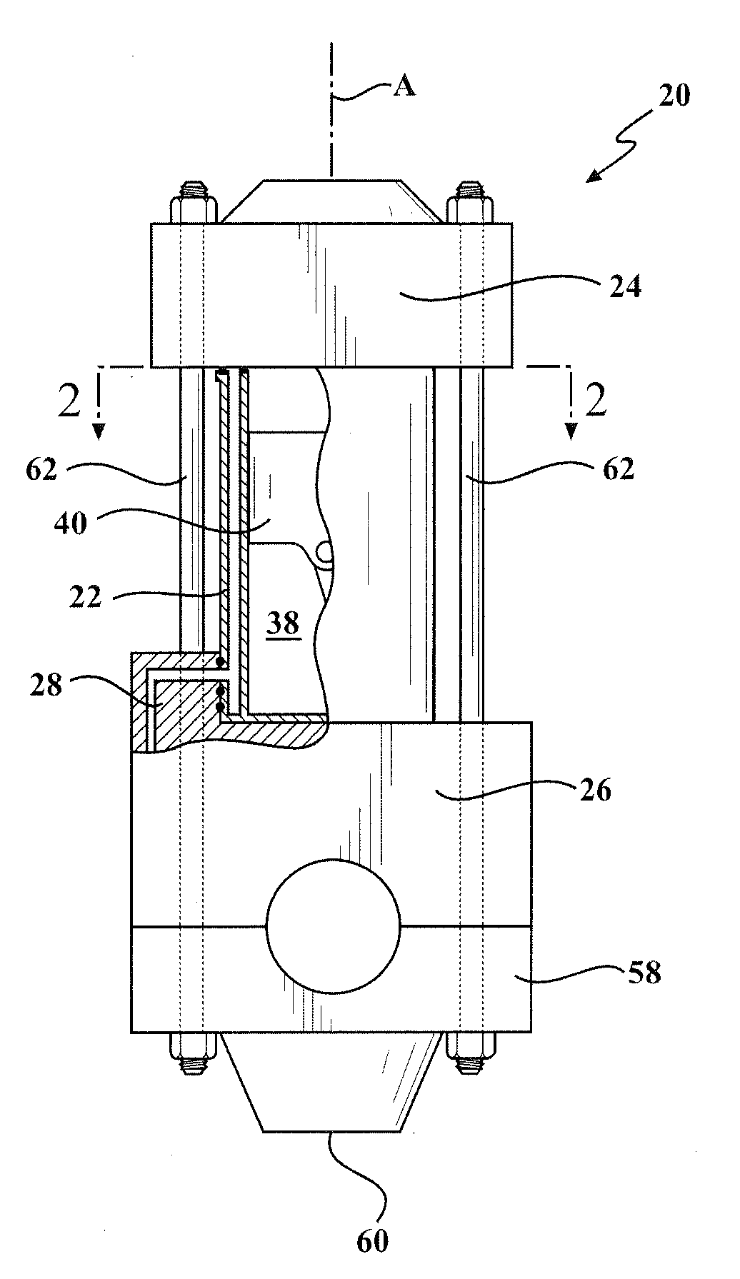
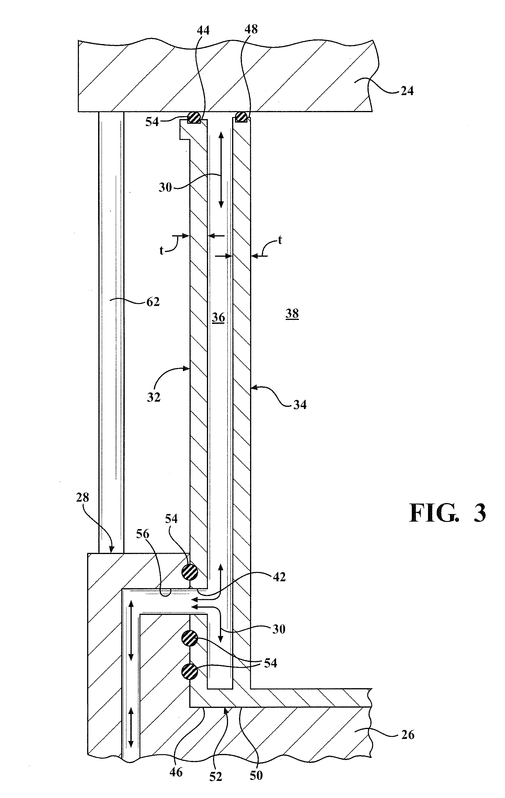
[0016]One aspect of the invention provides a robust engine assembly 20 for a gasoline or diesel internal combustion engine having a reduced total weight and efficient cooling, without an undesirable increase in fuel consumption or carbon dioxide emissions. The engine assembly 20 includes a double-wall cylinder liner 22 clamped between a cylinder head 24 and a crankcase 26. The engine assembly 20 also includes a manifold 28 disposed along a portion of the cylinder liner 22 for conveying cooling fluid 30 to or from the cylinder liner 22.

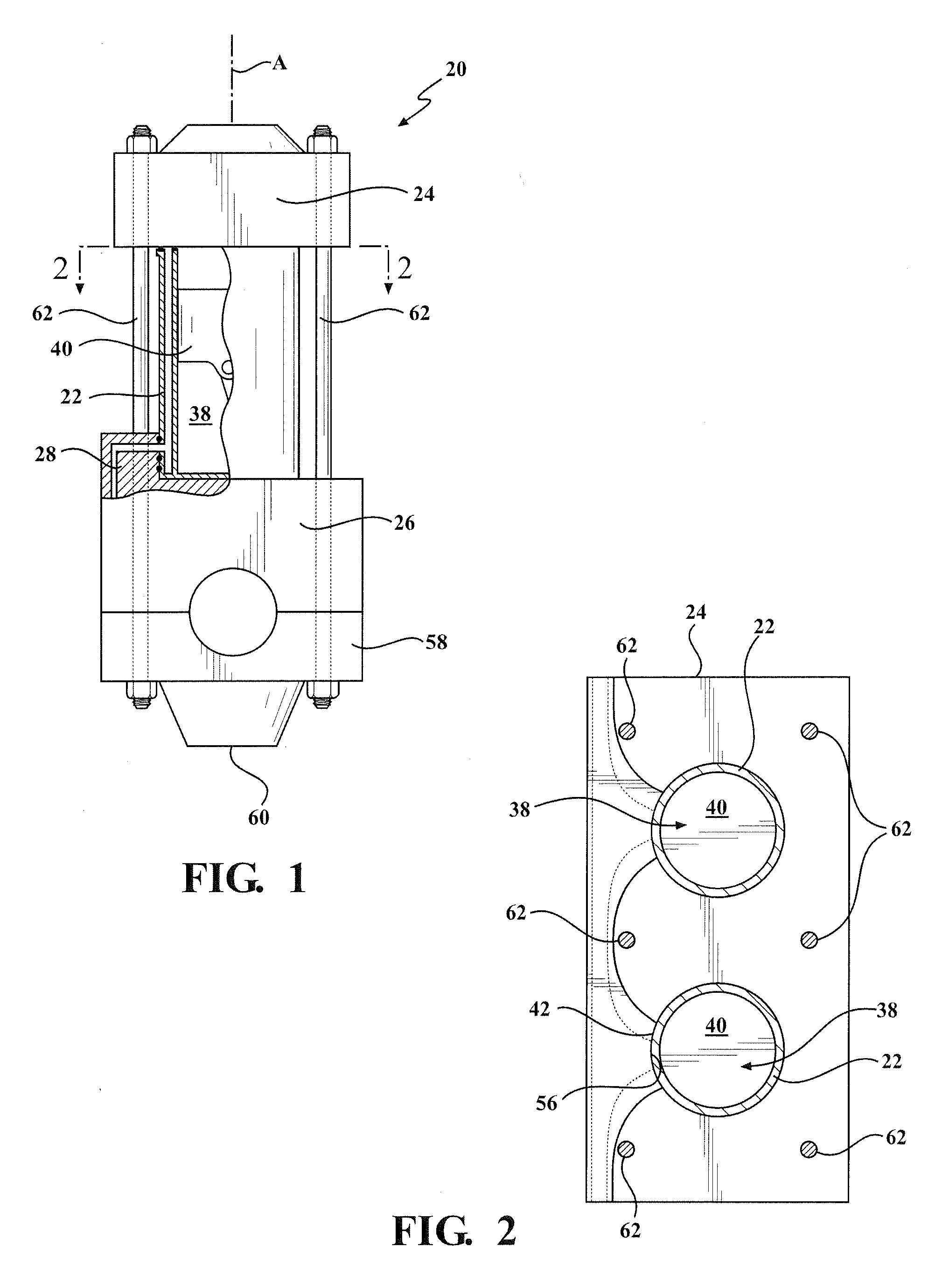
[0017]An exemplary engine assembly 20 including the double-wall cylinder liner 22, cylinder head 24, crankcase 26, and manifold 28 is shown in FIGS. 1-3. As shown, the engine assembly 20 is preferably designed without an engine block or cooling jacket, which significantly reduces the total weight of the engine.

[0018]In the exemplary embodiment, the cylinder liner 22 includes an outer wall 32 and an inner wall 34 presenting a cooling chamber 36 therebet...


PUM


Abstract

A robust engine assembly having reduced weight and efficient cooling, without an increase in fuel consumption or carbon dioxide emissions, is provided. The engine assembly includes a double-wall cylinder liner clamped between a cylinder head and a crankcase. A manifold is disposed along a portion of the cylinder liner and includes fluid ports aligned with fluid ports of the cylinder liner to convey cooling fluid to a cooling chamber located between the walls of the cylinder liner. For example, the manifold can be a low-loss hydraulic manifold cast integral with the crankcase. Tie rods connect the cylinder head to the crankcase to clamp the cylinder liner in position. Alternatively, the tie rods can be connected to a main bearing cradle located beneath the crankcase. No attachment features extend into the walls of the cylinder liner, which is especially advantageous when the cylinder liner is formed of aluminum.

Description

BACKGROUND OF THE INVENTION[0001]1. Field of the Invention[0002]This invention relates generally to internal combustion engine assemblies including cylinder liners, and methods of manufacturing the same.[0003]2. Related Art[0004]Manufacturers of internal combustion engines continuously strive to reduce the total weight of the engine, which in turn reduces fuel consumption and carbon dioxide emissions. For example, heavy duty diesel engine blocks formed of compact graphite cast iron have been designed using complex metallurgical casting processes and sophisticated and costly sculpturing of their external walls in order to reduce the total weight of the engine. However, smaller diesel engines shed greater amounts of heat than typical diesel engines. For example, the cooling needs of a typical internal combustion diesel engine amounts to about 20-25% of the heat input given off by the fuel burned, while the smaller engines typically shed even greater amounts of heat, reaching from abou...

Claims


Application Information

Patent Timeline
Patent Type & Authority Applications(United States)
IPC IPC(8): F02F1/16F02F1/24F02F1/10F02F1/00
CPCF02F1/16F02F1/102F02F1/24F02F1/004F02F1/10
Inventor AZEVEDO, MIGUEL
Owner FEDERAL MOGUL MOTORPARTS LLC
Why Eureka
Try Eureka