Methods and systems for transport-of-intensity imaging

Active Publication Date: 2016-05-19
NANYANG TECH UNIV
View PDF11 Cites 18 Cited by
  • Summary
  • Abstract
  • Description
  • Claims
  • Application Information

AI Technical Summary

Benefits of technology

[0020]These schemes proposed by the embodiment offer the possibility to extend TIE phase imaging to the study of fast moving objects and structural changes

Problems solved by technology

However, in general the phase information obtained through such means is neither linear nor quantitative, yielding only qualitative descriptions in terms of optical path-length measurement.
However, this class of method typically relies on two-beam interference with a high degree of coherence and thus is usually plagued with problems of phase aberration and coherent noise that prevent accurate phase retrieval and formation of high quality images.
However, despite its evident merits and great improvements, TIE-phase imaging techno

Method used


Image

  • Methods and systems for transport-of-intensity imaging
  • Methods and systems for transport-of-intensity imaging
  • Methods and systems for transport-of-intensity imaging

Examples


first embodiment

1. First Embodiment

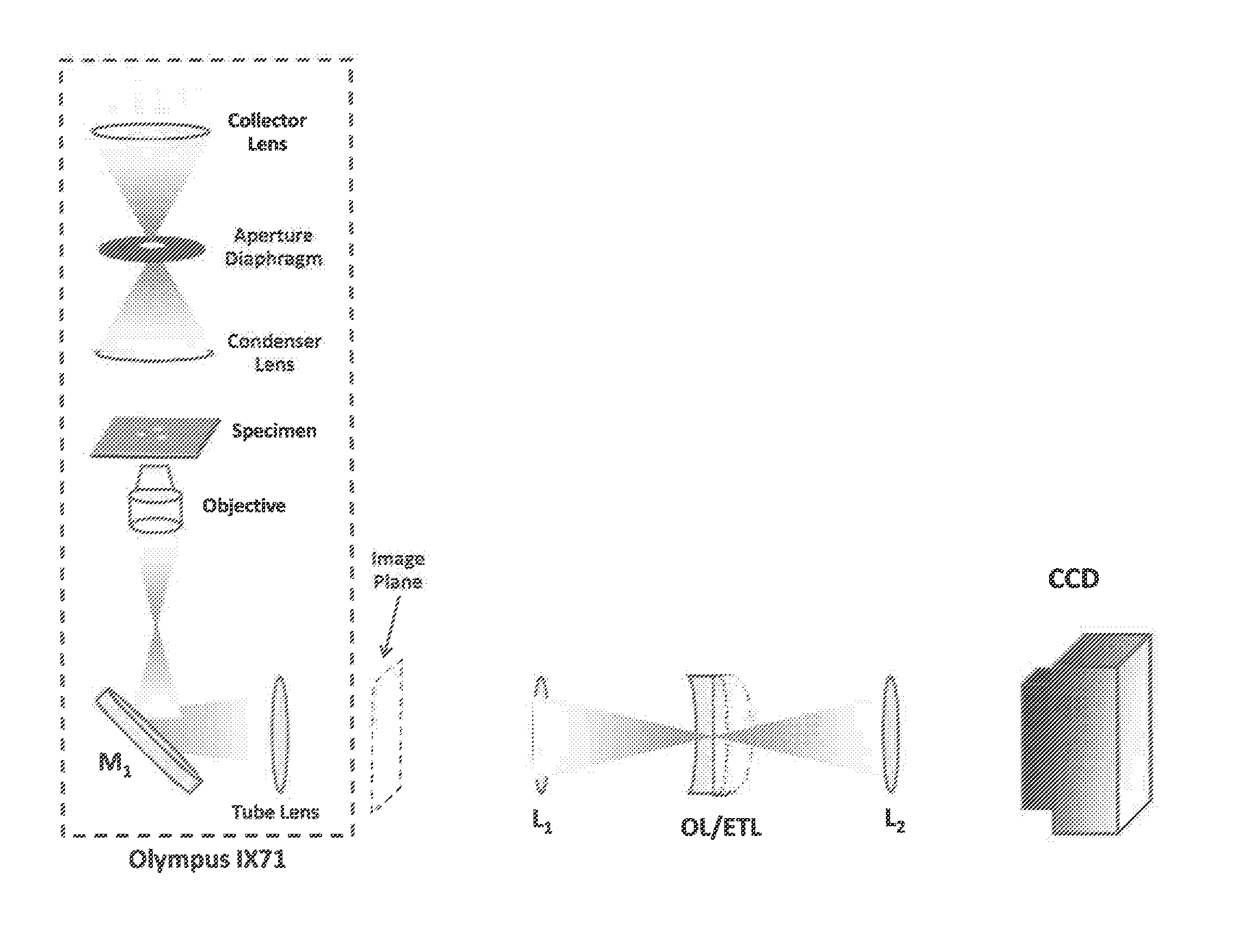
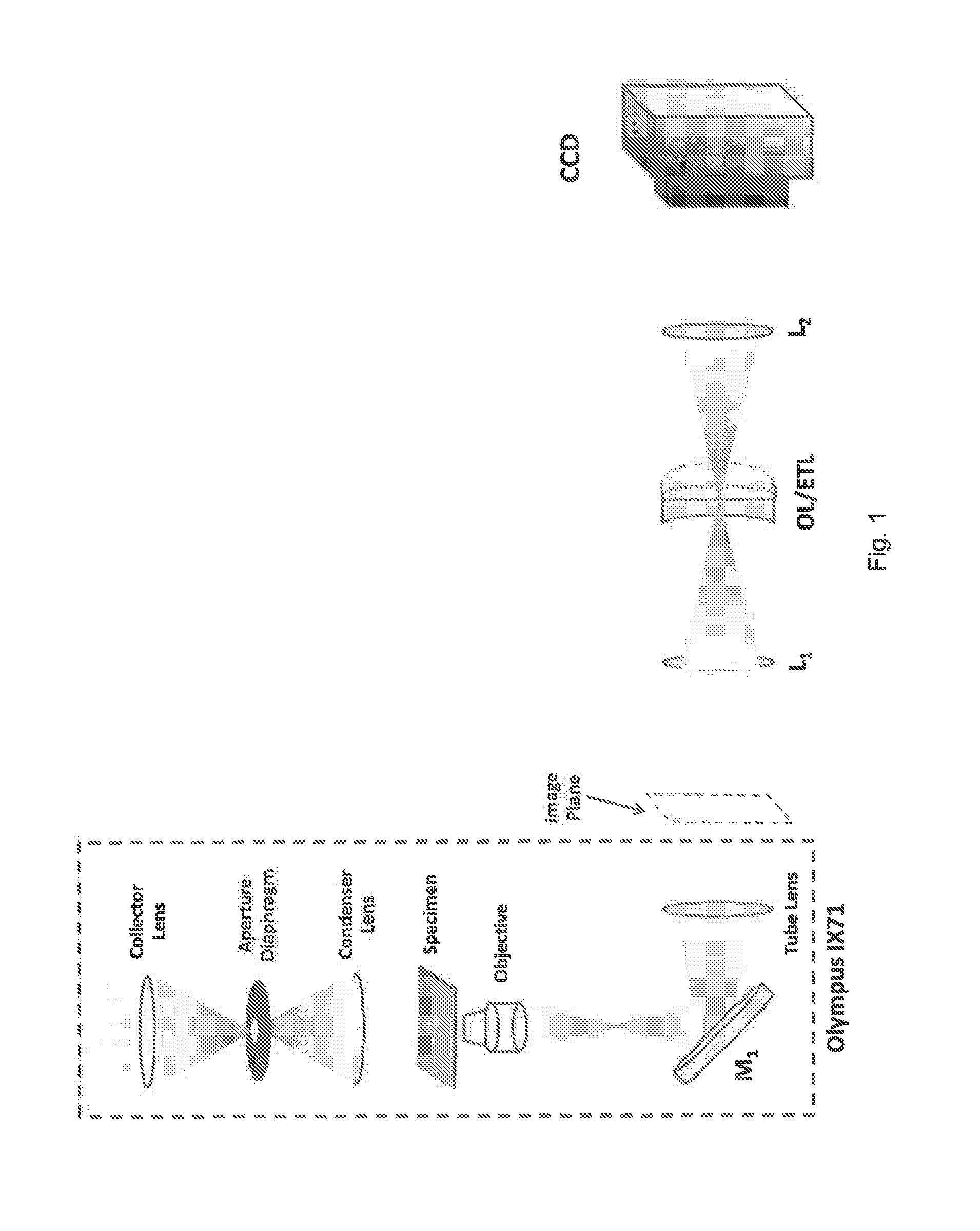
[0030]The first embodiment is a TIE system which employs a tunable lens (TL) for achieving high speed transport of intensity imaging. The setup is shown schematically in FIG. 1. The embodiment is obtained by adding a novel image relay system to the camera port of a conventional microscope. In the example below this is a commercial inverted microscope used in the transmission mode, but note that the principle would work for other microscopes, and can be used independently of whether the microscope is operated in the transmission or reflection mode.

[0031]At the left FIG. 1 is the conventional inverted bright field microscope system, designated Olympus IX71, which comprises a collector lens, a condenser aperture diaphragm, a condenser lens, an objective, a reflective mirror (M1), and a tube lens. An specimen to be imaged is located on a support between the condenser lens and objective. The microscope produces a magnified image of the specimen at the camera output por...

second embodiment

2. Second Embodiment

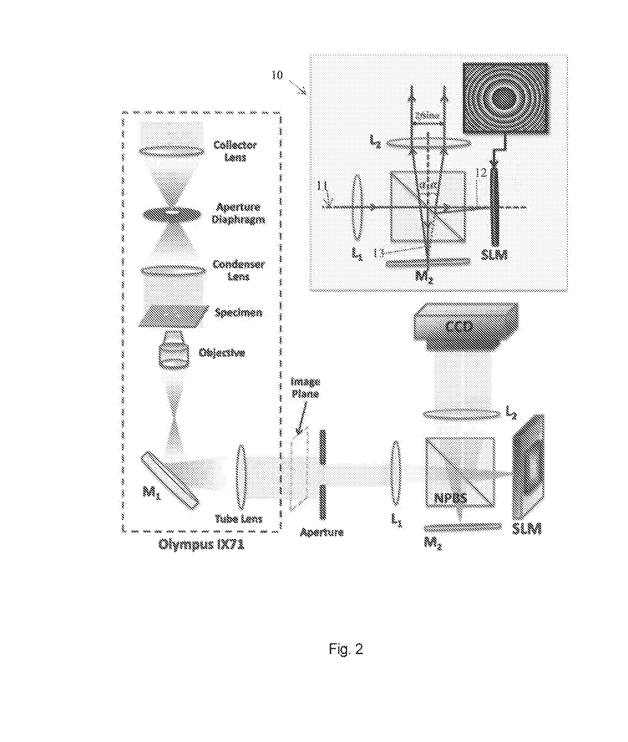
[0048]The second schematic setup for achieving single-shot transport of intensity imaging is shown in FIG. 2, including an inset portion 10 which explains the operation of the system. It also employs a commercial inverted microscope (again referred to as an Olympus IX71) with an additional 4f image relay system. All the requirements and specifications of the microscope and the 4f system are same as mentioned above for the first embodiment.

[0049]In contrast to the first embodiment, a non-polarizing cube beam splitter (NPBS) splits the image beam11 into two beams 12, 13. A spatial light modulator (SLM) (located at the Fourier plane) reflects one of these beams (in particular, beam 12) and the second beam 13 is reflected from a plane mirror (M2) located at the Fourier plane. Theoretically, the total distance travelled by the light between the two lenses L1 and L2 is equal to 2f irrespective of which beam 12 or 13 is considered.

[0050]However, in practice, depending o...


PUM


Abstract

A transport-of-intensity imaging system is proposed which incorporates a control element positioned in an optical relay system, such as a 4f optical relay system, between a microscope system for generating an image of a specimen, and an image capturing device. The control element is located with an optical relay system, and is controllable to vary the focal plane without changing the spacing of the specimen and the image capturing device. In one form the control element is an electronically tunable lens (ETL). In another form, the control element is a spatial light modulator (SLM). The arrangement may include a beam splitter arrangement for generating a plurality of beams, which are not all subject to the same control element, such that multiple images with different focal planes are captured from the respective beams.

Description

FIELD OF THE INVENTION[0001]The present invention relates to methods and systems for transport-of-intensity imaging. In particular, it relates to methods and systems which are suitable for imaging subjects which are evolving over time, and which have to be repeatedly imaged at short time intervals, for example with time intervals of less than a second, or more preferably less than a tenth of a second. This is referred to here as imaging for a dynamics application.BACKGROUND OF THE INVENTION[0002]Over the past decade, a great deal of scientific attention has been paid to quantitative phase imaging, which has emerged as an important tool for phase visualization and structure retrieval of miniature non-absorbing specimens such as micro-optical elements, unstained cells, and other types of biological and transparent technical samples. Zernike phase contrast [1] and differential interference contrast microscopy [2] have proven to be extremely powerful imaging tools for visualization of p...

Claims


Application Information

Patent Timeline
IPC IPC(8): G02B21/00
CPCG02B21/008G02B21/0032G02B21/006G02B26/06G02B27/10G02B21/365
Inventor ASUNDI, ANAND KRISHNAZUO, CHAO
Owner NANYANG TECH UNIV
Why Eureka
Try Eureka