
Lens Moving Apparatus

a technology of moving apparatus and moving body, which is applied in the field of moving apparatus, can solve the problems of difficulty in adopting voice coil motor (vcm) technology, camera module mounted in a small-sized electronic product such as a smart phone, may be frequently subjected to shock during use, and camera module may minute shake, so as to reduce the driving force for handshake correction and increase durability.

Active Publication Date: 2016-05-19
LG INNOTEK CO LTD
View PDF7 Cites 37 Cited by
  • Summary
  • Abstract
  • Description
  • Claims
  • Application Information

AI Technical Summary

Benefits of technology

This patent describes a new way to move a lens in a camera to correct for handshake. The new approach reduces the amount of force needed to correct for handshake and makes the camera more durable. It also simplifies the structure of the lens moving apparatus and allows for accurate and rapid handshake correction. Overall, this technology improves the performance and reliability of camera modules.

Problems solved by technology

It is difficult to adopt voice coil motor (VCM) technology, which is typically used in conventional camera modules, for use in an ultracompact camera module, which aims at achieving low power consumption, and thus research into the technology has been actively undertaken.
A camera module mounted in a small-sized electronic product, such as a smart phone, may be frequently subjected to shocks during use.
In addition, the camera module may minutely shake due to the trembling of the user's hand while taking a photograph.

Method used


Image

  • Lens Moving Apparatus
  • Lens Moving Apparatus
  • Lens Moving Apparatus

Examples


first embodiment

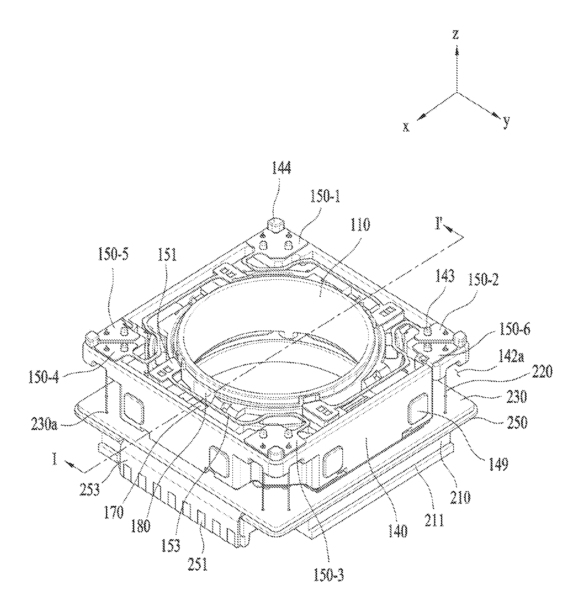
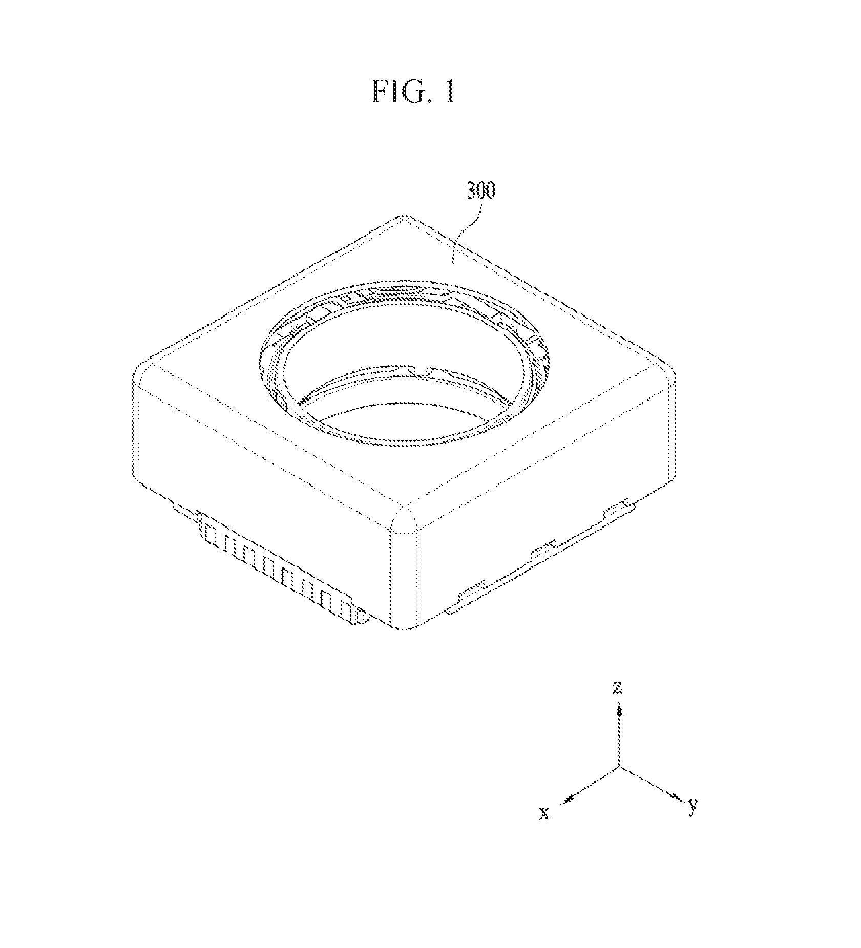
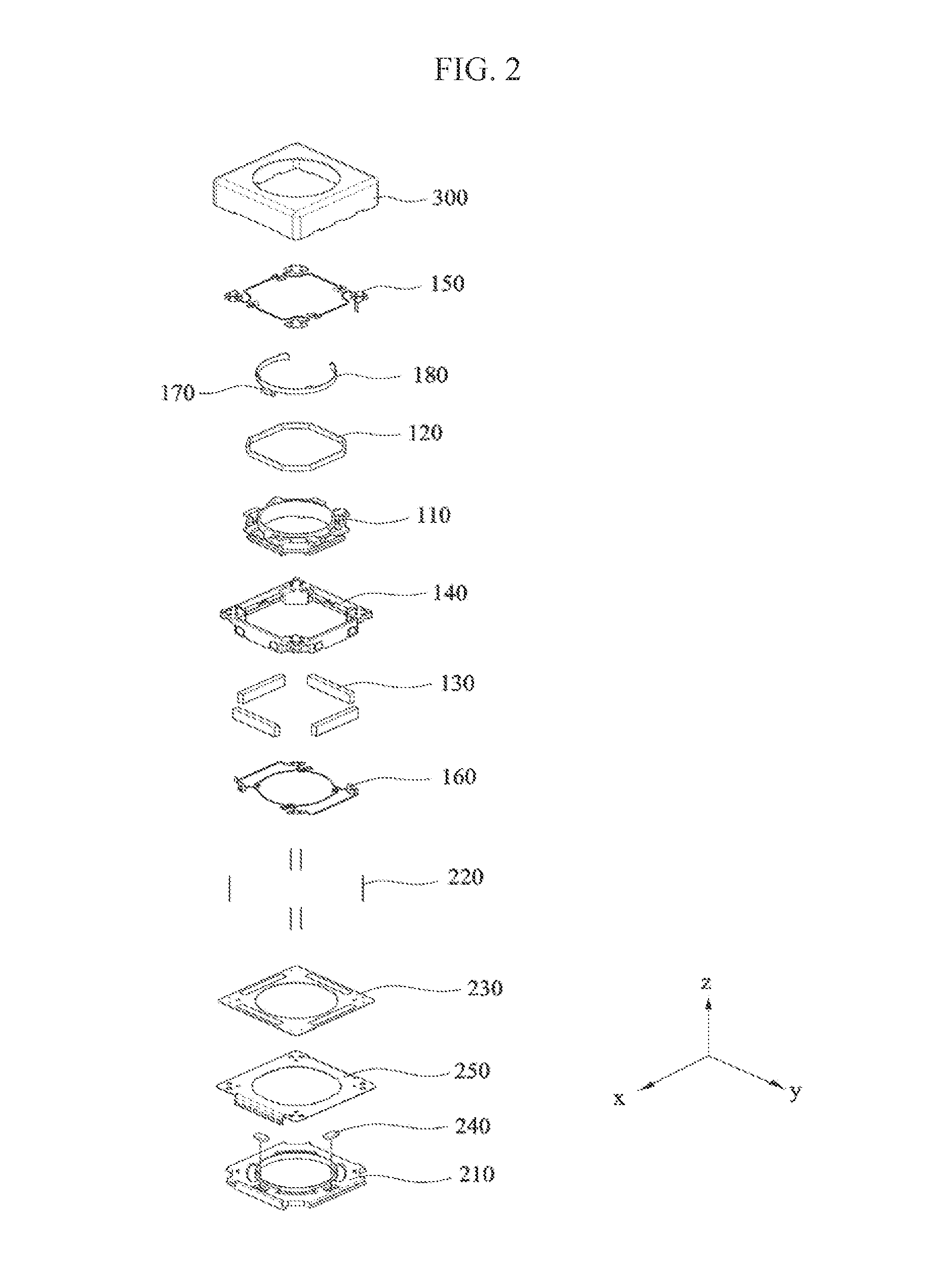
[0046]FIG. 1 is a schematic perspective view showing a lens moving apparatus according to a first embodiment. FIG. 2 is an exploded perspective view of the lens moving apparatus shown in FIG. 1.

[0047]Referring to FIGS. 1 and 2, the lens moving apparatus according to the embodiment may include a first lens moving unit, a second lens moving unit, and a cover member 300.

[0048]The first lens moving unit may serve as the above-mentioned autofocusing apparatus. In other words, the first lens moving unit may serve to move a bobbin 110 in the first direction by virtue of the interaction between a magnet 130 and a first coil 120.

[0049]The second lens moving unit may serve as the handshake correction apparatus. In other words, the second lens moving unit may serve to move all or a portion of the first lens moving unit in the second and / or third directions by virtue of the interaction between the magnet 130 and the second coil 230.

[0050]The cover member 300 may be configured to have an approxi...

second embodiment

[0206]FIG. 15 is a perspective view showing a lens moving apparatus according to a second embodiment of the present invention. FIG. 16 is an exploded perspective view showing the lens moving apparatus according to the second embodiment.

[0207]As shown in FIGS. 15 and 16, the lens moving apparatus according to this embodiment may include a movable unit. The movable unit may fulfill the functions of autofocusing and handshake correction of a lens. The movable unit may include a bobbin 110, a first coil 120, a first magnet 130, a housing 140, an upper elastic member 150 and a lower elastic member 160.

[0208]The bobbin 110 may be provided in the housing 300, and the first coil 120, which is disposed inside the first magnet 130, may be provided on the outer circumferential surface of the bobbin 110. The bobbin 110 may be reciprocated in the first direction in the internal space of the housing 140 by electromagnetic interaction between the first magnet 130 and the first coil 120. The first ...


PUM


Abstract

A lens moving apparatus includes a bobbin including a first coil disposed therearound, a first magnet disposed to face the first coil, a housing for supporting the first magnet, upper and lower elastic members each coupled to both the bobbin and the housing, a base disposed to be spaced apart from the housing by a predetermined distance, a second coil disposed to face the first magnet, a printed circuit board on which the second coil is mounted, a plurality of support members, which support the housing such that the housing is movable in second and / or third directions and which connect at least one of the upper and lower elastic members to the printed circuit board, and a conductive member for conductively connecting the upper and lower elastic members.

Description

CROSS REFERENCE TO RELATED APPLICATIONS[0001]This application claims priority under 35 U.S.C. §119 to Korean Application Nos. 10-2014-0158683, filed on Nov. 14, 2014 and 10-2014-0158686, filed on Nov. 14, 2014, which are hereby incorporated by reference in their entirety.TECHNICAL FIELD[0002]Embodiments relate to a lens moving apparatus.BACKGROUND[0003]It is difficult to adopt voice coil motor (VCM) technology, which is typically used in conventional camera modules, for use in an ultracompact camera module, which aims at achieving low power consumption, and thus research into the technology has been actively undertaken.[0004]A camera module mounted in a small-sized electronic product, such as a smart phone, may be frequently subjected to shocks during use. In addition, the camera module may minutely shake due to the trembling of the user's hand while taking a photograph. Therefore, there is a high necessity for a technology capable of incorporating an optical image stabilizer into t...

Claims


Application Information

Patent Timeline
IPC IPC(8): G02B27/64H01F27/32G03B5/04G02B7/02G03B5/02H01F27/28H01F7/20
CPCG02B27/646H01F27/2804H01F27/325G03B5/04G02B7/023G03B5/02H01F7/20G02B7/04G02B7/09G02B7/08
Inventor PARK, SANG OKMIN, SANG JUN
Owner LG INNOTEK CO LTD
Features
  • Generate Ideas
  • Intellectual Property
  • Life Sciences
  • Materials
  • Tech Scout
  • Unparalleled Data Quality
  • Higher Quality Content
  • 60% Fewer Hallucinations
Learn More