
Wireless power transmitting apparatus

Active Publication Date: 2016-05-19
LG ELECTRONICS INC
View PDF8 Cites 36 Cited by
  • Summary
  • Abstract
  • Description
  • Claims
  • Application Information

AI Technical Summary

Benefits of technology

The wireless power transmitter described in this patent can operate for a longer time in a wider area. This means that it can provide power to devices that are further away from the transmitter and can also be used in a wider range of temperatures and environments. This is achieved by improving the design of the transmitter and its components.

Problems solved by technology

However, the wireless charging device has a narrow charging area due to a size of its transmitting coil.
For an inductive wireless charging device, there has been a disadvantage in that a receiving coil of a portable device (or a mobile device) and a transmitting coil of the charging device should be aligned with each other at a (re)charging operation.
Also, for the charging device allowing the X and Y-axial movement of the transmitting coil, the charging area may be ensured without a reduction of charging efficiency but an increase in fabricating costs and difficulty in development and production may be caused due to mechanical complexity of the transfer unit.

Method used


Image

  • Wireless power transmitting apparatus
  • Wireless power transmitting apparatus
  • Wireless power transmitting apparatus

Examples


Embodiment Construction

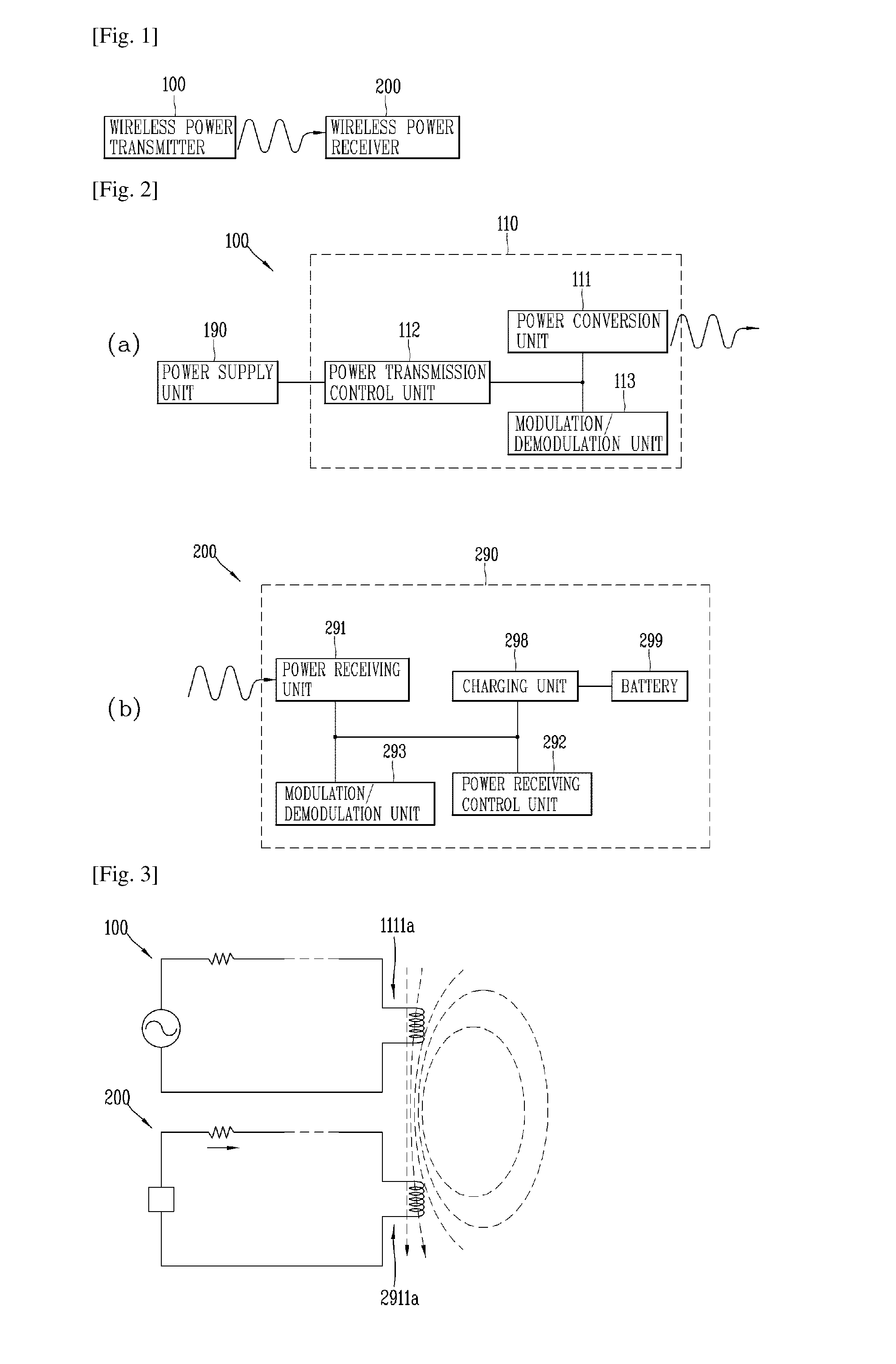
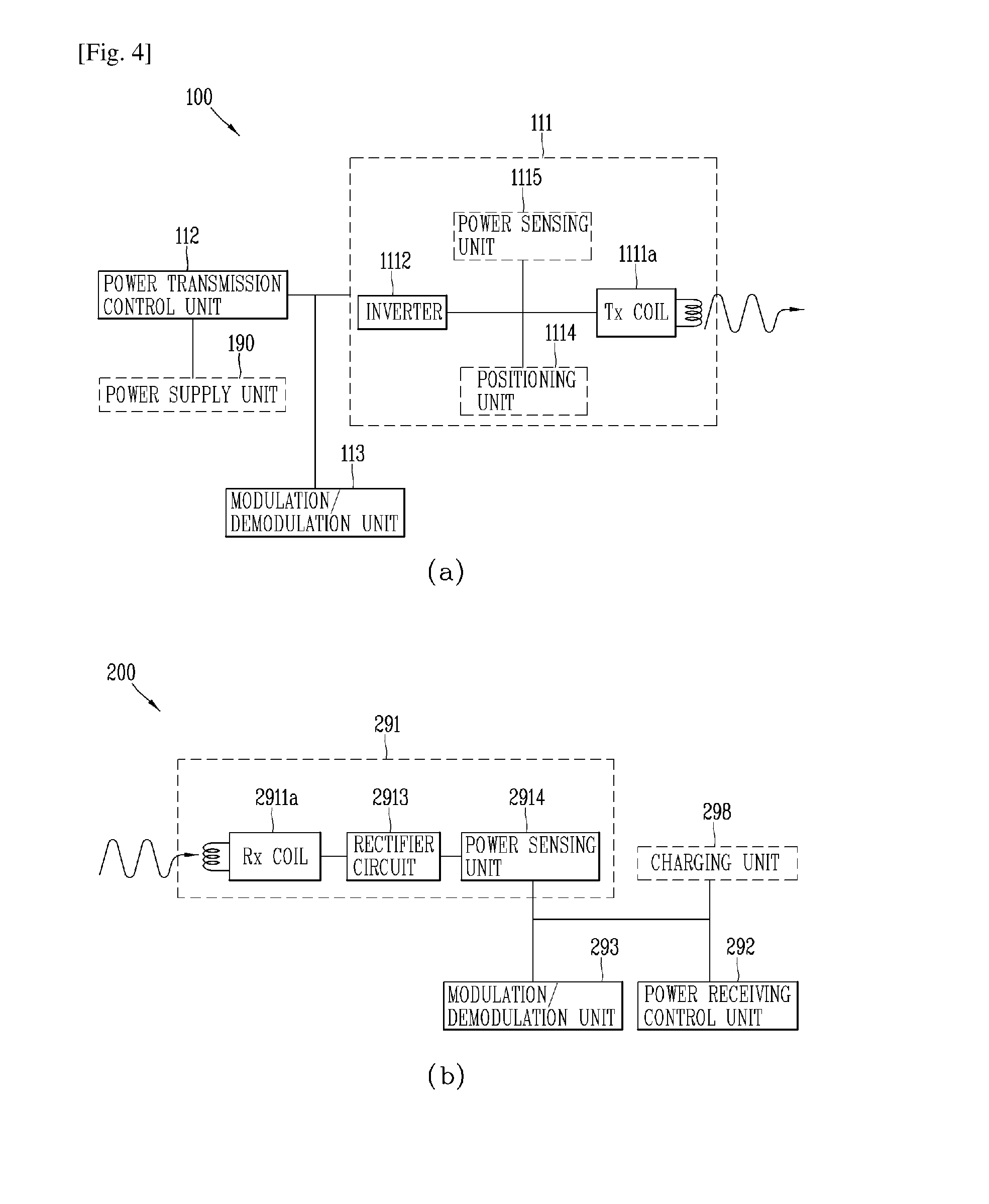
[0040]The technologies disclosed herein may be applicable to wireless power transfer (contactless power transfer). However, the technologies disclosed herein are not limited to this, and may be also applicable to all kinds of power transmission systems and methods, wireless charging circuits and methods to which the technological spirit of the technology can be applicable, in addition to the methods and apparatuses using power transmitted in a wireless manner.

[0041]It should be noted that technological terms used herein are merely used to describe a specific embodiment, but not to limit the present invention. Also, unless particularly defined otherwise, technological terms used herein should be construed as a meaning that is generally understood by those having ordinary skill in the art to which the invention pertains, and should not be construed too broadly or too narrowly. Furthermore, if technological terms used herein are wrong terms unable to correctly express the spirit of the...


PUM


Abstract

A wireless power transmitter according to one exemplary embodiment of the present disclosure includes a body having a transmitting coil unit embedded therein, and having one surface with a portable electronic device located thereon, the portable electronic device receiving power from the transmitting coil unit in a wireless manner, and a driving unit that is configured to rotate the transmitting coil unit centering on a shaft penetrating through the transmitting coil unit, such that the transmitting coil unit is moved close to a receiving coil unit of the portable electronic device.

Description

TECHNICAL FIELD[0001]The present disclosure relates to a wireless power transfer, and more particularly, a wireless power transmitter (or a wireless power transmitting apparatus) having an extended operation area by a new structure of a transmitting coil upon a wireless power transfer.BACKGROUND ART[0002]Recently, an increase in power consumption by smart phones, tablet PCs and the like has derived development of various types of wireless charging devices (or chargers) for portable devices which should be frequently recharged. However, the wireless charging device has a narrow charging area due to a size of its transmitting coil. For an inductive wireless charging device, there has been a disadvantage in that a receiving coil of a portable device (or a mobile device) and a transmitting coil of the charging device should be aligned with each other at a (re)charging operation. Due to the narrow charging area, demands of product developers and consumers are increasing for a continuous ...

Claims


Application Information

Patent Timeline
IPC IPC(8): H02J5/00H02J7/02
CPCH02J5/005H02J7/025H02J17/00H02J50/12H02J7/00308H02J50/90H02J7/00304H02J50/80H02J50/40H02J7/0044
Inventor LEE, HYUNBEOMJUNG, KIHYUN
Owner LG ELECTRONICS INC
Learn More