Colour marking metal surfaces

a technology of colour marking and metal surfaces, applied in the field of colour marking metal surfaces, can solve the problems of inflexible processes, limited methods, and inability to adapt to changing conditions, and achieve the effect of durable against wear and corrosion

Active Publication Date: 2016-05-26
CAJO TECH
View PDF10 Cites 9 Cited by
  • Summary
  • Abstract
  • Description
  • Claims
  • Application Information

AI Technical Summary

Benefits of technology

[0007]Embodiments of the invention provide several advantages. The markings realized with the embodiments are very durable against wear and corrosion. Practically any multicolour graphical image may be marked onto a metal or steel surface. In general, a metal surface may be matted on shining or have other variable properties. In an embodiment, the marking process leaves these properties and surface quality of the metal surface visible regardless of the marking.

Problems solved by technology

These methods are very limited and the processes are not flexible.
The markings and colours are not durable.
In addition, the methods may involve the use of paints and solvents which are harmful to environment.
However, practical applications of the known techniques have not been proposed and the obtained markings are simple.

Method used


Image

  • Colour marking metal surfaces
  • Colour marking metal surfaces
  • Colour marking metal surfaces

Examples


Embodiment Construction

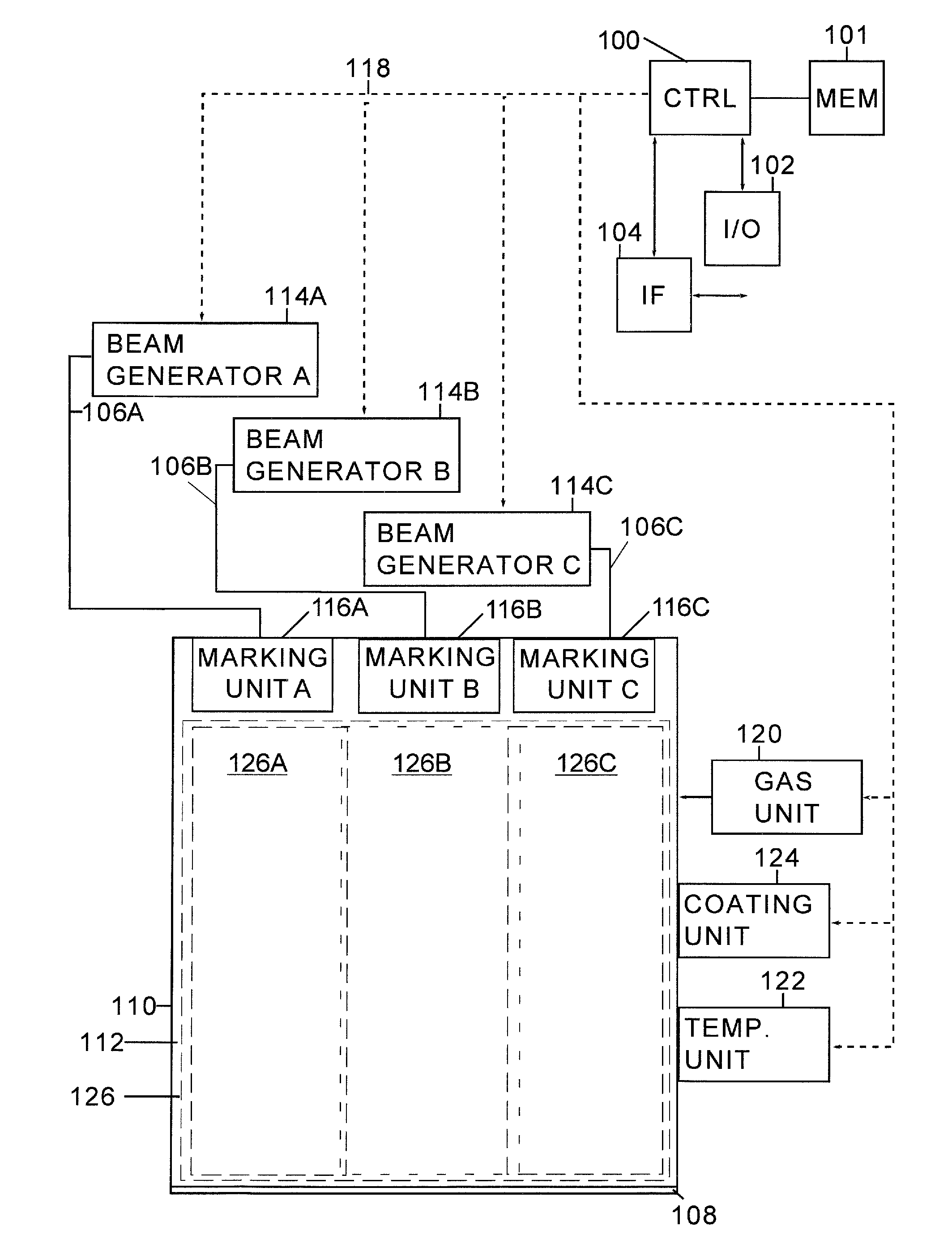
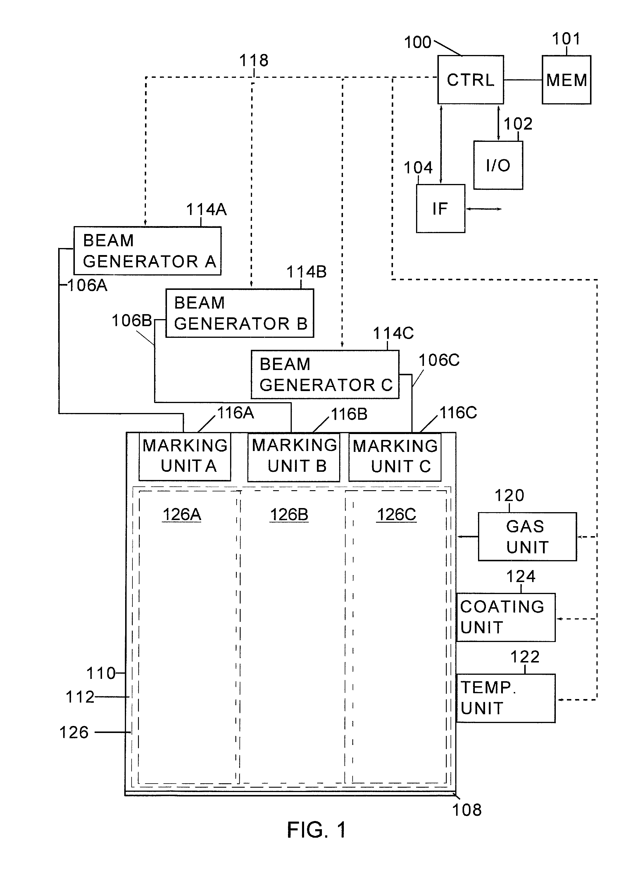
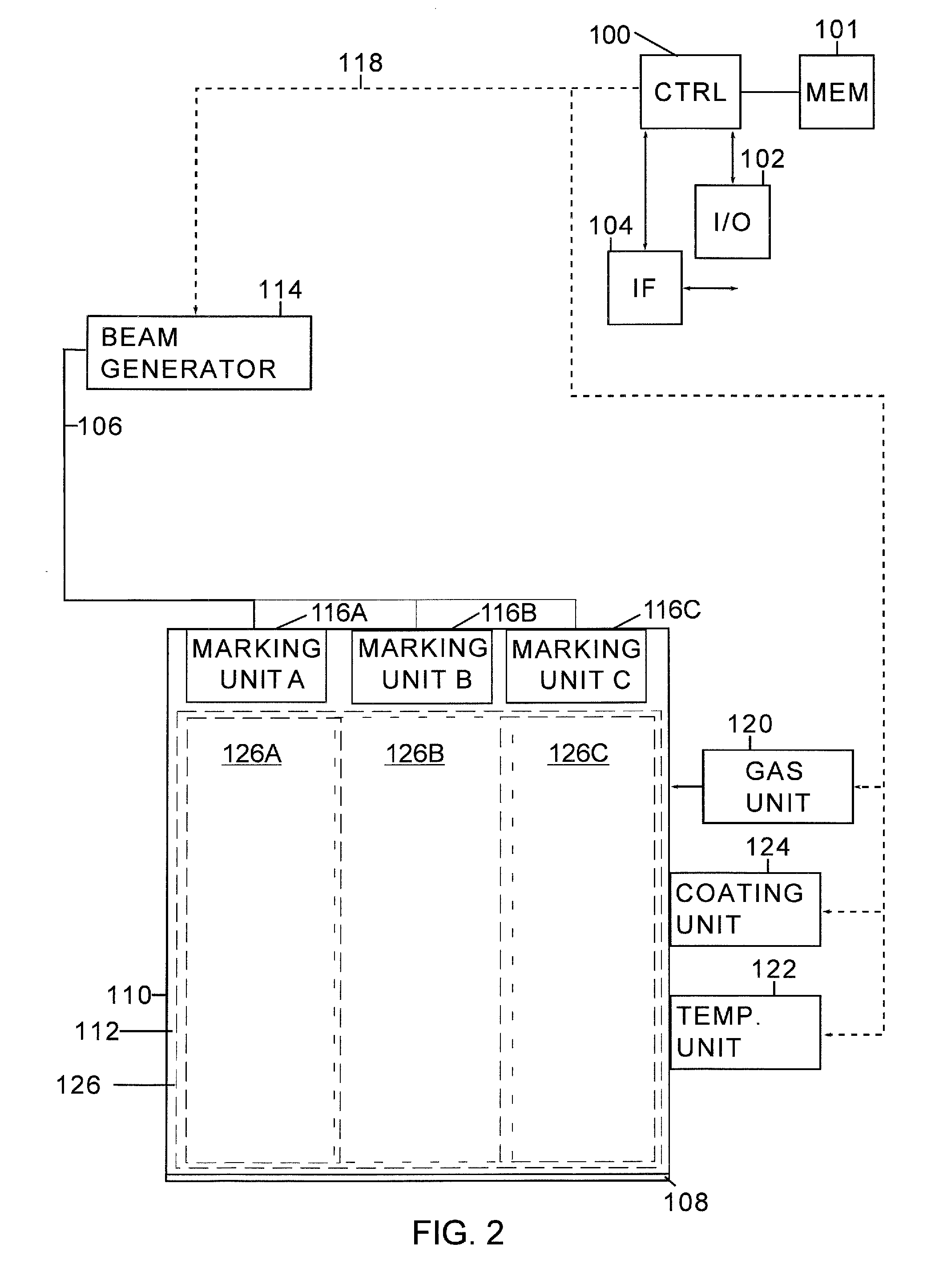
[0016]FIG. 1 illustrates a schematic example of an apparatus suitable for marking or colouring objects having metal or steel surfaces. It should be understood that the apparatus is depicted herein as an example illustrating some embodiments. It is apparent to a person skilled in the art that the apparatus may also comprise other functions and / or structures and not all described functions and structures are required. The figure is purely schematic and the actual location of the units of a realized apparatus may be different as one skilled in the art is aware. The apparatus comprises a controller unit or control circuitry 100. The controller unit or control circuitry is typically realized with at least one processor; and at least one memory 101 including computer program code, the at least one memory and the computer program code configured to control the operation of the apparatus. The controller unit or control circuitry 100 may comprise an input / output unit 102 either as a separate...


PUM

PropertyMeasurementUnit
thicknessaaaaaaaaaa
areaaaaaaaaaaa
movementaaaaaaaaaa

Abstract

Apparatus related to marking a metal surface are provided. The solution includes a bed for an object including a metal surface, the bed including a total marking area; a cover forming an airtight space over the bed; one or more laser marking units capable of directing a laser beam onto the metal surface located within a unit marking area, wherein the unit marking area is smaller than the total marking area. In the proposed solution control data including information on the marking of a pattern on the metal surface is received; the focus, bandwidth and movement of the one or more laser marking units is controlled on the basis of the control data to produce the pattern defined in the control data on the metal surface.

Description

FIELD[0001]The exemplary and non-limiting embodiments of the invention relate generally to marking or colouring steel surfaces.BACKGROUND[0002]The following description of background art may include insights, discoveries, understandings or disclosures, or associations together with disclosures not known to the relevant art prior to the present invention but provided by the invention. Some of such contributions of the invention may be specifically pointed out below, whereas other such contributions of the invention will be apparent from their context.[0003]Metal or steel surfaces are in many applications marked or coloured with various marks or colours. The purpose may be esthetical or sometimes the purpose is to protect the surface. A common method for colouring metal surfaces is to use paints, adhesive labels, etching or electrolytic colouring. These methods are very limited and the processes are not flexible. This applies especially applications where different markings are requir...

Claims


Application Information

Patent Timeline
Patent Type & Authority Applications(United States)
IPC IPC(8): B23K26/362B23K26/08B23K26/04B23K26/06B05D7/14B23K26/12
CPCB23K26/362B05D7/14B23K26/127B23K26/0884B23K26/123B23K26/0604B23K26/04B41J2/455G06K1/126G06K19/0614B41M5/24B41M5/262B23K26/352B23K26/0869B44C1/005G06K1/12B23K26/032C23C10/00B44C1/228B44B7/007B23K26/361
Inventor KARSIKAS, TOMIKARSIKAS, NIKO
Owner CAJO TECH
Why Eureka
Try Eureka