Eureka AIR delivers breakthrough ideas for toughest innovation challenges, trusted by R&D personnel around the world.

Torque wrench

Inactive Publication Date: 2016-05-26
KAE MAE ENTERPRISE
View PDF4 Cites 3 Cited by
  • Summary
  • Abstract
  • Description
  • Claims
  • Application Information

AI Technical Summary

Benefits of technology

The present invention is a torque wrench that aims to solve the issue of requiring calibration to correct the effect of spring characteristics and mechanical wear over time. The technical effect is to provide a more efficient and effective solution for tightening and loosening bolts and screws.

Problems solved by technology

However, these gages can be hard to read, especially when the user is occupied with torquing a fastener with smooth and continuous motion to achieve proper fastening Moreover, the size of the markings is often small and the resolution of the markings is often limited by the physical space available on the gage.
Besides, calibration of the wrenches often requires disassembling the unit to replace worn out parts, which can be expensive and time consuming.
And, calibration is often needed to correct the effect of the spring's characteristics and mechanical wear that occurs over time.
Often, such wear cannot be compensated for without calibration since the gages are most often permanently printed on the handle.

Method used


Image

  • Torque wrench
  • Torque wrench
  • Torque wrench

Examples


Embodiment Construction

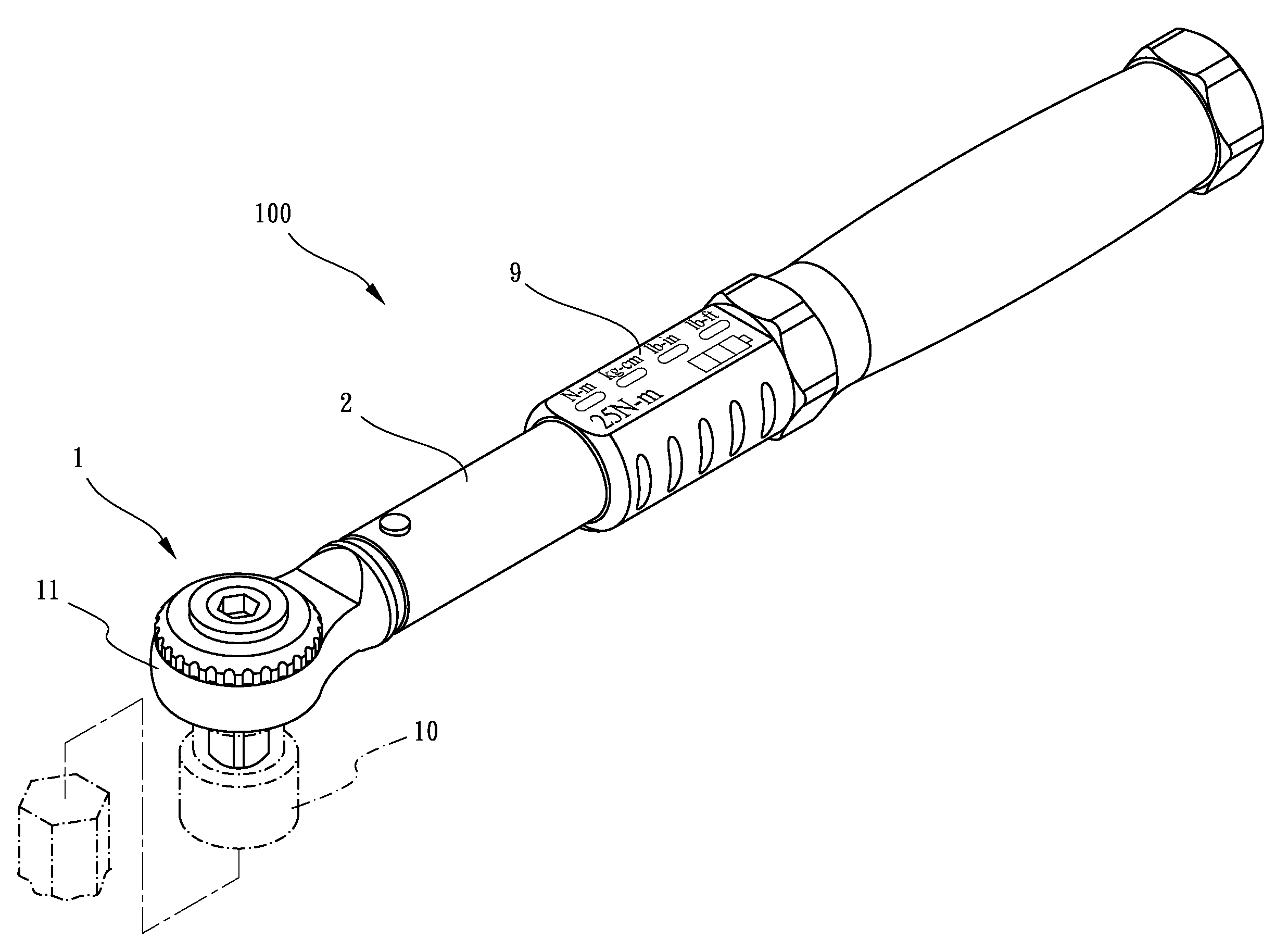
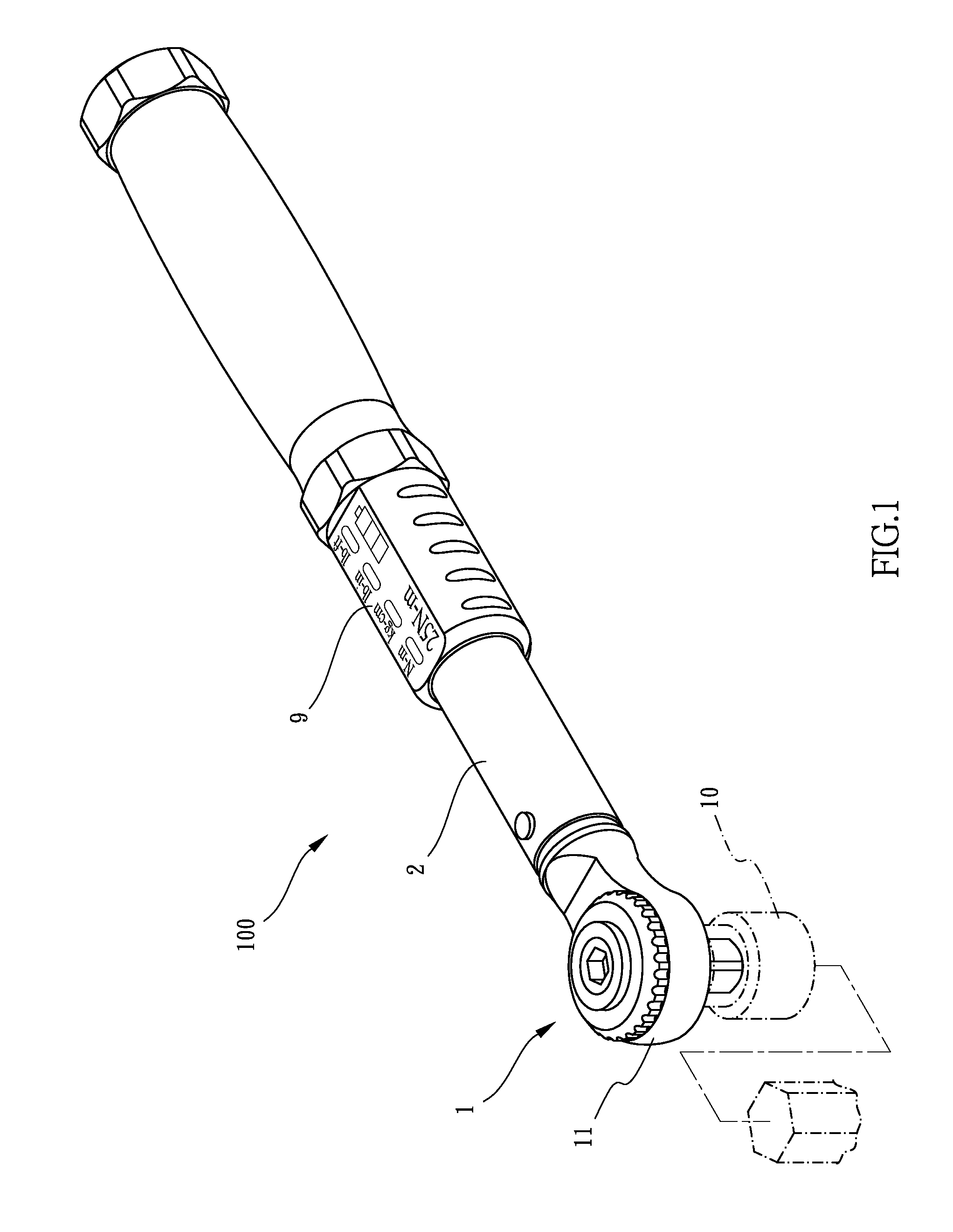
[0018]Referring now to the drawings for a more detailed description of the present invention and more particularly to FIGS. 1 and 2, a novel torque wrench made according thereto is generally indicated by the reference numeral 100. The torque wrench 100 as shown includes a wrench head 1, an elongated, tubular wrench body 2, parts within the tubular wrench body 2, and a display 9 on the wrench body 2 for indicating a preset torque to be applied by the torque wrench 100 to a workpiece 10.

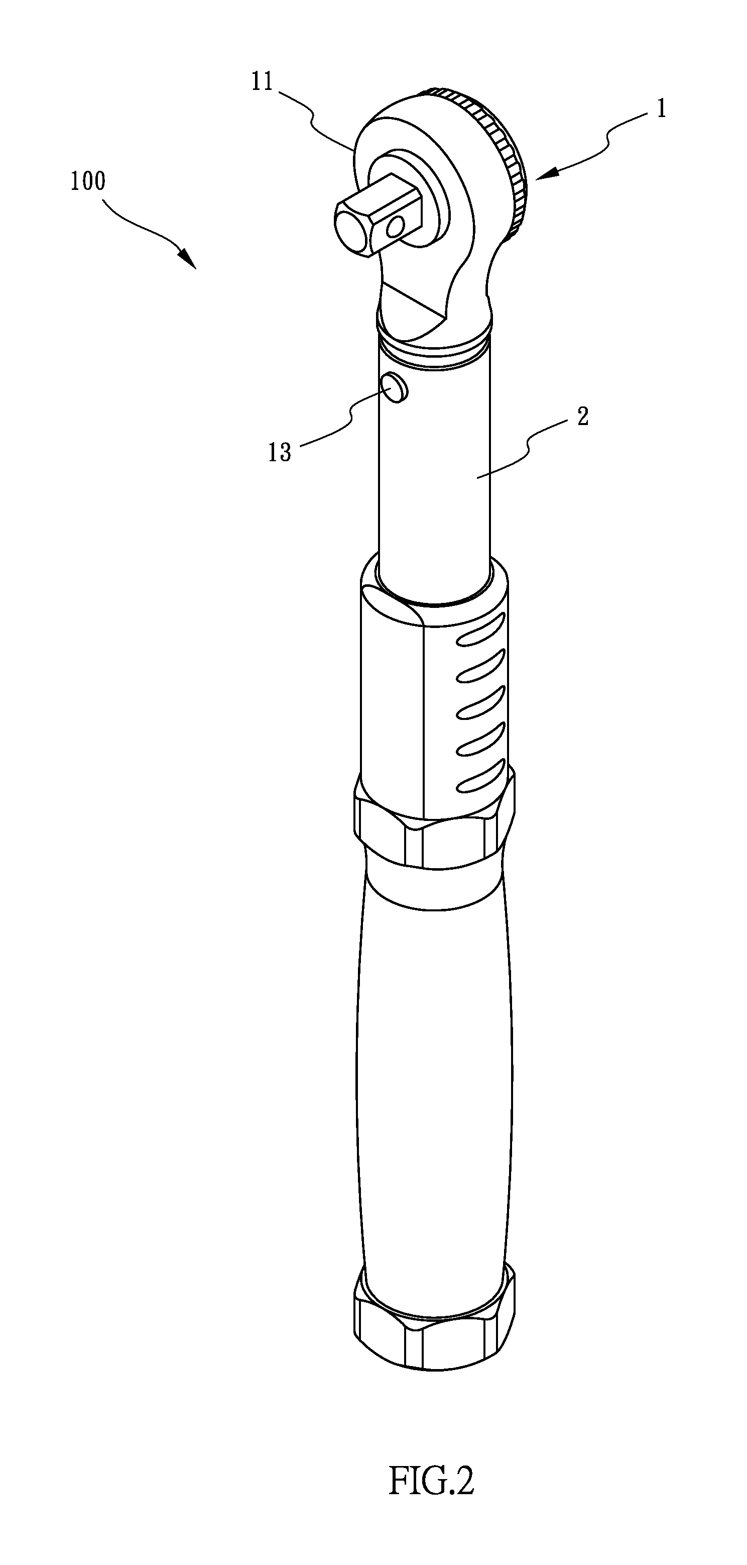
[0019]As shown in FIG. 3, the wrench head 1, such as a ratchet-type head, has a drive portion 11 and a bar 12 extending from the drive portion 11. The drive portion 11 is constructed to be removably engaged with the workpiece 10 (see FIG. 1). The bar 12 is inserted within a front end of the wrench body 2. The wrench head 11 and the wrench body 2 are pivotally connected by a pivot pin 13 for pivotal movement relative to one another.

[0020]Within the wrench body 2 are a pawl 23, a plunger 3, a piezoelectr...


PUM


Abstract

A torque wrench includes a wrench body, a wrench head pivotally carried by the arm, a plunger, a pawl, a spring for urging the plunger, and an adjustment assembly. The adjustment assembly is operatively connected to the spring to vary an effective force of the spring on the plunger. The piezoelectric sensor is interposed in between the plunger and the spring for producing an output signal in response to the effective force exerted by the spring. A processor is provided for converting the output signal into an equivalent torque value, the equivalent torque value indicating a preset torque to be applied by the torque wrench to the workpiece. A display is further employed for displaying the equivalent torque value. Application of a torque greater than the preset torque to the workpiece causes the wrench head to pivot relative to the wrench body about a pivot joint.

Description

BACKGROUND OF THE INVENTION[0001]1. Field of the Invention[0002]The present invention relates to a torque wrench for applying a pre-determined amount of torque to a fastener, and is more particularly concerned with a torque wrench having means for precisely setting a preset torque for the wrench.[0003]2. Description of the Related Art[0004]Torque wrenches are well known in the art. They vary from simple mechanical types to sophisticated electronic types. There are several types of mechanical torque wrenches that are routinely used to tighten fasteners to specified torque levels.[0005]One example of a mechanical torque wrench is illustrated in U.S. Pat. Nos. 5,435,190 or 6,463,834, which makes an audible click to let the user know when a preset torque level has been achieved and simultaneously provide a feeling of sudden torque release to the user. This torque wrench generally includes a hollow tube in which a spring and pawl mechanism is housed. The pawl is forced against one end of...

Claims


Application Information

Patent Timeline
IPC IPC(8): B25B23/142
CPCB25B23/1422B25B23/1425B25B23/1427
Inventor JIANG, ZHENG-CONG
Owner KAE MAE ENTERPRISE
Why Eureka
Eureka Blog
Learn More