Motor vehicle and cam-type pushing force brake apparatus of electric vehicle

A technology of braking device and electric vehicle, which is applied to mechanical drive drum brakes, hydraulic drum brakes, brake actuators, etc., can solve the problems of low utilization rate of brake pads and inability to adjust the effective arm of the brake arm, etc. Achieve the effect of avoiding rainwater corrosion and rust, increasing the length and improving the utilization rate

Active Publication Date: 2015-04-29
CHONGQING BANGHUA MACHINERY MFG
View PDF9 Cites 6 Cited by
  • Summary
  • Abstract
  • Description
  • Claims
  • Application Information

AI Technical Summary

Problems solved by technology

[0005] The technical problem to be solved by the present invention is to provide a cam-type thrust brake device for motor vehicles and electric vehicles with brake pads for the low utilization rate of the brake pads in the prior art and the non-adjustable effective force arm of the brake arm. The characteristics of high utilization rate and adjustable effective force arm of the brake arm

Method used


Image

  • Motor vehicle and cam-type pushing force brake apparatus of electric vehicle
  • Motor vehicle and cam-type pushing force brake apparatus of electric vehicle
  • Motor vehicle and cam-type pushing force brake apparatus of electric vehicle

Examples


Embodiment 1

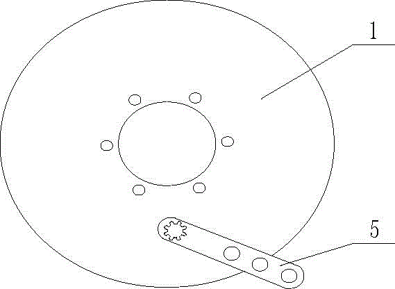
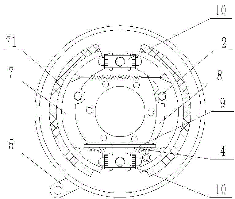
[0036] Such as figure 1 , figure 2 , image 3 , Figure 4 , Figure 5 As shown, the cam-type thrust braking device for motor vehicles and electric vehicles includes a brake base plate 1, two positioning mechanisms 2, two first return springs 3, two second return springs 4, a brake arm 5, and a cam Axle 6, two arc-shaped brake shoes 7, a hand brake lever 8, a support plate 9, a brake cylinder 10, two adjusting push rods 11 and an adjusting device. The adjustment device, the brake cylinder body 10 and the support plate 9 are all located between the two arc-shaped brake shoes 7 . The handbrake lever 8 is connected to the brake bottom plate 1 through a pin shaft, and the end of the handbrake lever 8 is in contact with the support plate 9 . The adjusting device comprises an adjusting tube 14, two screw rods 141 are installed in the adjusting tube 14, nuts are arranged on the screw rods 141, grooves are arranged at the ends of the screw rods 141, and a plurality of grooves are...

Embodiment 2

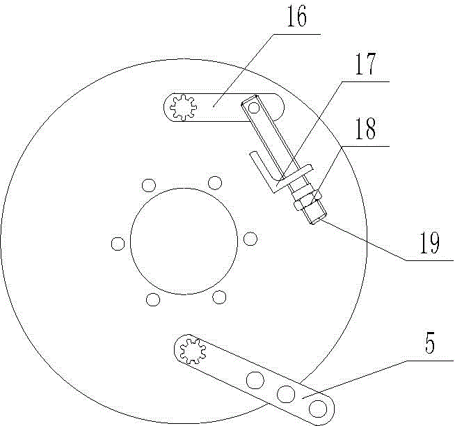
[0039] The difference between embodiment two and embodiment one is: as Figure 10 , Figure 11 As shown, the adjustment device is replaced by a cam type device.

[0040] The cam type device includes a brake cylinder block 10 , a camshaft 6 , an adjusting push rod 11 , a rotating arm 16 , a support base 17 , an adjusting pull rod 19 and a locking nut 18 . The rotating arm 16 is splined connected with the camshaft 6 , the rotating arm 16 is hinged with the adjusting pull rod 19 through a pin shaft, and the adjusting pull rod 19 is threadedly connected with the locking nut 18 . The support seat 17 is welded on the back side of the brake bottom plate 1 . The support base 17 is provided with a through hole for the adjustment rod 19 to pass through. Support seat 17 selects angle steel for use.

[0041] In the specific implementation process, the locking nut 18 is rotated, so that the adjusting rod 19 drives the rotating arm 16 to rotate, and the rotating arm 16 drives the camsha...

Embodiment 3

[0043] The difference between embodiment three and embodiment two is: as Figure 12 , Figure 13 , Figure 14 As shown, the second through hole in the brake cylinder is replaced by the first blind hole 22, and the positioning plate 20 is provided on the brake base plate 1, and the positioning plate 20 and the brake base plate 1 are connected by screws. The camshaft 6 is replaced by a double fulcrum camshaft 21 . The double fulcrum camshaft 21 is sequentially composed of a first rotating part, a second rotating part of the camshaft and a connecting part from top to bottom. The connecting part is a spline shaft. The positioning plate 20 is provided with a rotating hole matched with the second rotating part, and the first rotating part of the double fulcrum camshaft 21 is connected with the first blind hole 22 .


PUM


Abstract

The invention discloses a motor vehicle and a cam-type pushing force brake apparatus of an electric vehicle. The motor vehicle comprises a brake baseboard, a locating mechanism, a reset spring, a brake arm, a camshaft and two brake shoes; the locating mechanism is arranged among said brake shoes and the brake baseboard, wherein said brake shoes are respectively provided with a brake pad, the camshaft is rotationally connected with the brake baseboard and the brake arm is detachably connected with the camshaft; the motor vehicle further comprises a brake cylinder which is arranged on the brake baseboard, a cavity for rotating the cam part on the camshaft is arranged in the brake cylinder, the brake cylinder is longitudinally provided with two first through holes which are respectively arranged on both ends of the brake cylinder, the brake cylinder is radially provided with a second through hole and a third through hole, and the first, second and third through holes are respectively connected with the cavity; an adjusting mandrel is arranged in the first through hole. The motor vehicle can overcome disadvantage that the utilization rate of the brake pad of the mechanical braking device is low and the effective force arm isn't adjustable in the existing technology.

Description

technical field [0001] The invention belongs to the field of brake devices for light-duty vehicles, in particular to a cam-type thrust brake device for motor vehicles and electric vehicles. Background technique [0002] At present, the braking system of light-duty motor vehicles and electric vehicles generally adopts the braking method of the brake pads rubbing against the side of the hub, that is, the brake handle on the handlebar is connected to the braking part. When braking, the brake handle drives the brake pads through the steel cable to make the brake pads rub against the hub so that the hub brakes to achieve the braking effect. At present, light-duty motor vehicles and electric vehicles are divided into hydraulic braking and mechanical braking according to the braking method. Hydraulic braking is to supply hydraulic oil to the piston cavity in the braking system through the hydraulic station on the vehicle body, so that the piston rod pushes the brake shoes to make ...

Claims


Application Information

Patent Timeline
Patent Type & Authority Applications(China)
IPC IPC(8): F16D51/24F16D51/22F16D65/18F16D121/02F16D121/14F16D123/00F16D125/28
Inventor 李邦华
Owner CHONGQING BANGHUA MACHINERY MFG
Why Eureka
Try Eureka