

Cycle wheel rim and manufacturing method therefor
a technology for cycle wheels and rims, which is applied in the direction of spoked wheels, mechanical equipment, transportation and packaging, etc., can solve the problems of limited lightening of rims, reduced fatigue strength of materials, and reduced rims designed to receive inextensible beads
- Summary
- Abstract
- Description
- Claims
- Application Information
AI Technical Summary
Benefits of technology
Problems solved by technology
Method used
Image

Examples
first embodiment
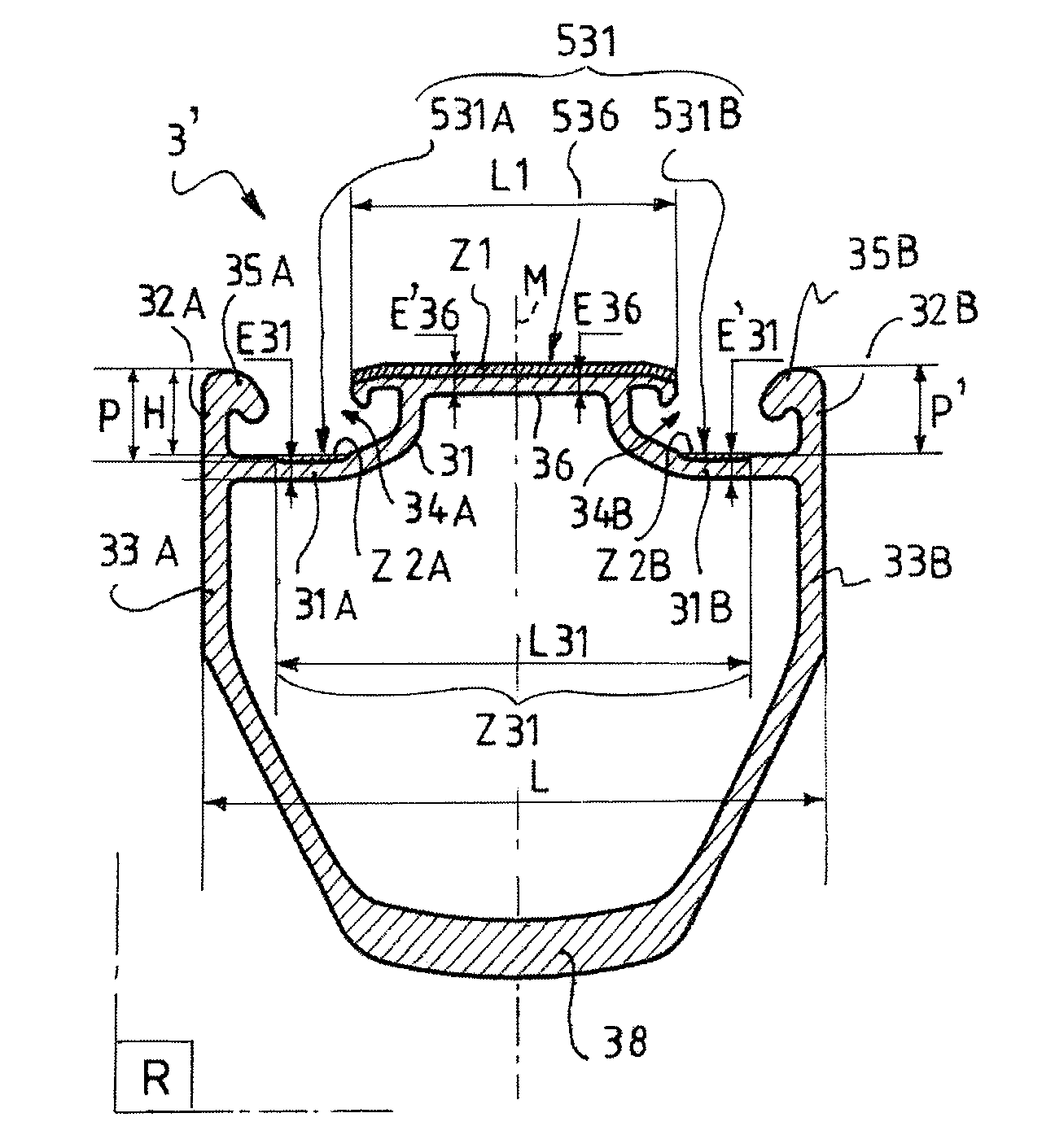
[0057]The interface zone has a maximum depth P, which corresponds to the difference in elevation between the top of the lateral flanges and the lowermost point of the upper bridge. In the invention, the maximum depth P corresponds to the difference in elevation between the bottom of the channel 34A or 34B and the top of the corresponding lateral flange 32A or 32B. The depth P is measured radially in a radial cross-sectional plane R of the rim 3, between the top of the lip 35A or 35B and the lateral outer surface 531A and 531B of the corresponding left 31A or right 31B lateral portion of the upper bridge 31. The depth P of the channel 34A is equal to that of the channel 34B.
[0058]The depth P is less than 7.0 mm or, in an alternative embodiment, less than 5.0 mm, or even on the order of 3.5 mm.
[0059]The tire 2 has the shape of an open torus. It comprises a flexible envelope 21 and two beads 6A and 6B. The envelope 21 is overlaid by a tread 22. In the embodiment described here, the env...
second embodiment
[0095]FIGS. 7 and 8 show a rim 1003 according to the invention. In the following description, the elements of the rim 1003 similar to those of the rim 3 are given the same reference numerals, increased by 1000, and are not described in detail. Only the elements of the rim 1003 that differ from those of the rim 3 are described below.
[0096]Similar to the rim 3, the rim 1003 comprises a lower bridge 1038, an upper bridge 1031, and two sidewalls 1033A and 1033B which, together, demarcate a volume V of the rim 1003. The sidewalls 1033A and 1033B are extended upward by lateral flanges 1032A and 1032B ended with lips 1035A and 1035B.
[0097]The upper bridge 1031 includees a median portion 1036 and two lateral portions 1031A and 1031B. The median portion 1036 is higher than the lateral portions 1031A and 1031B so as to demarcate channels 1034A and 1034B.
[0098]The method for manufacturing the rim 1003 is similar to that described with reference to the rim 3. The geometry of the milling cutter ...
third embodiment
[0100]FIG. 9 shows a rim 2003 according to the invention. In the following description, the elements of the rim 2003 similar to those of the rim 3 are given the same reference numerals, increased by 2000, and are not described in detail. Only the elements of the rim 2003 that differ from those of the rim 3 are described.
[0101]Similar to the rim 3, the rim 2003 comprises a lower bridge 2038, an upper bridge 2031, and two sidewalls 2033A and 2033B which, together, demarcate a volume V of the rim 2003. The sidewalls 2033A and 2033B are extended upward by lateral flanges 2032A and 2032B ended with lips 2035A and 2035B.
[0102]The upper bridge 2031 includes a median portion 2036 and two lateral portions 2031A and 2031B. The median portion 2036 comprises two projections 2036A and 2036B each ended by a stopper so as to demarcate channels 2034A and 2034B.
[0103]The method for manufacturing the rim 2003 is similar to that described with reference to the rim 3. The geometry of the milling cutter...
PUM
| Property | Measurement | Unit |
|---|---|---|
| Fraction | aaaaa | aaaaa |
| Thickness | aaaaa | aaaaa |
| Thickness | aaaaa | aaaaa |
Abstract
Description
Claims
Application Information