Felling saw recovery control

Active Publication Date: 2016-05-26
DEERE & CO
View PDF11 Cites 10 Cited by
  • Summary
  • Abstract
  • Description
  • Claims
  • Application Information

AI Technical Summary

Benefits of technology

[0007]This disclosure relates to tree felling saw heads

Problems solved by technology

However, prioritizing saw operation over the main hydraulic system has obvious disadvantages, including slowed or impaired operation of one or more other hydraulic systems of the machine.
Even so, such a control scheme often provides slow saw recovery relative to

Method used


Image

  • Felling saw recovery control
  • Felling saw recovery control
  • Felling saw recovery control

Examples


Embodiment Construction

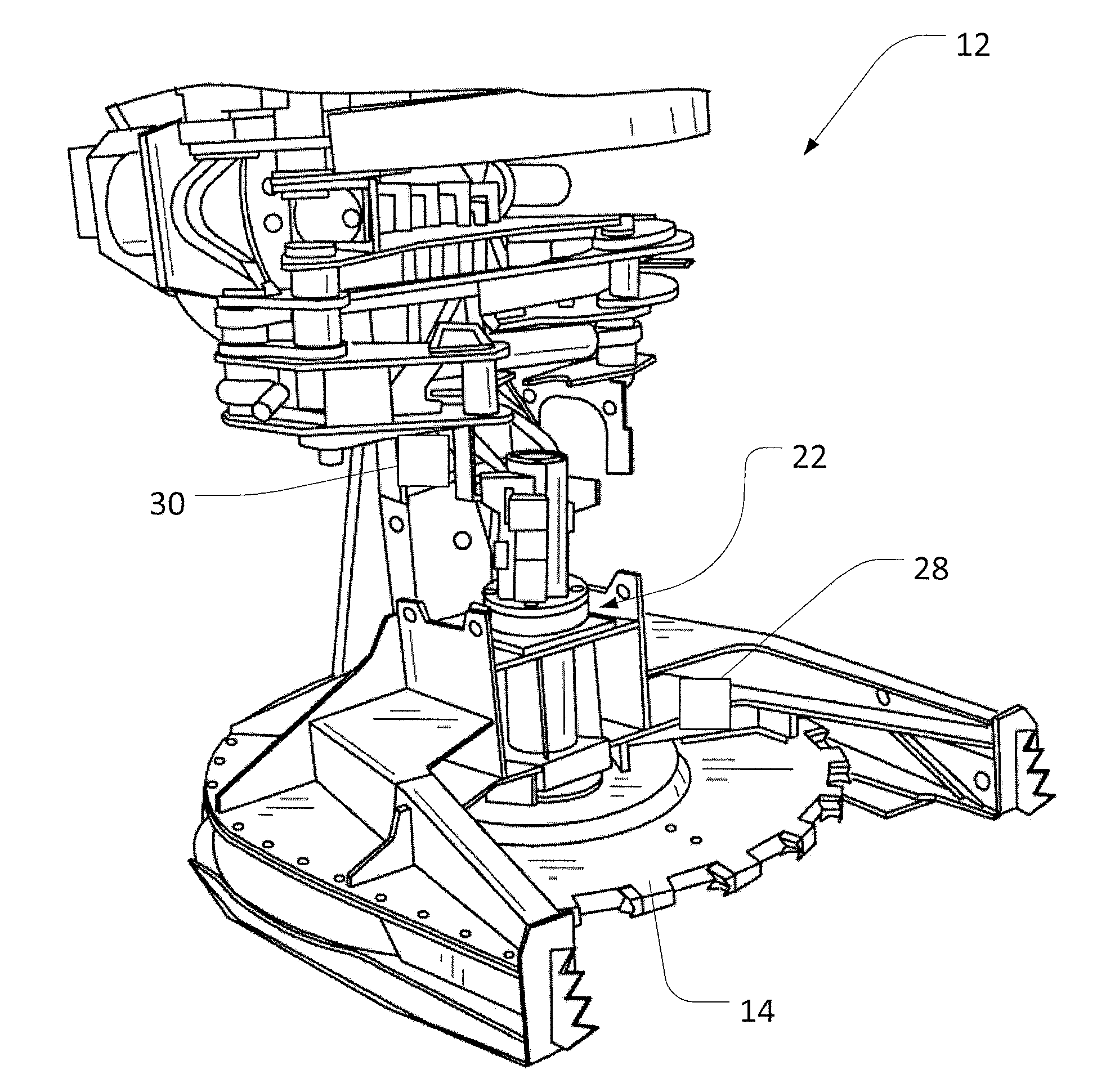
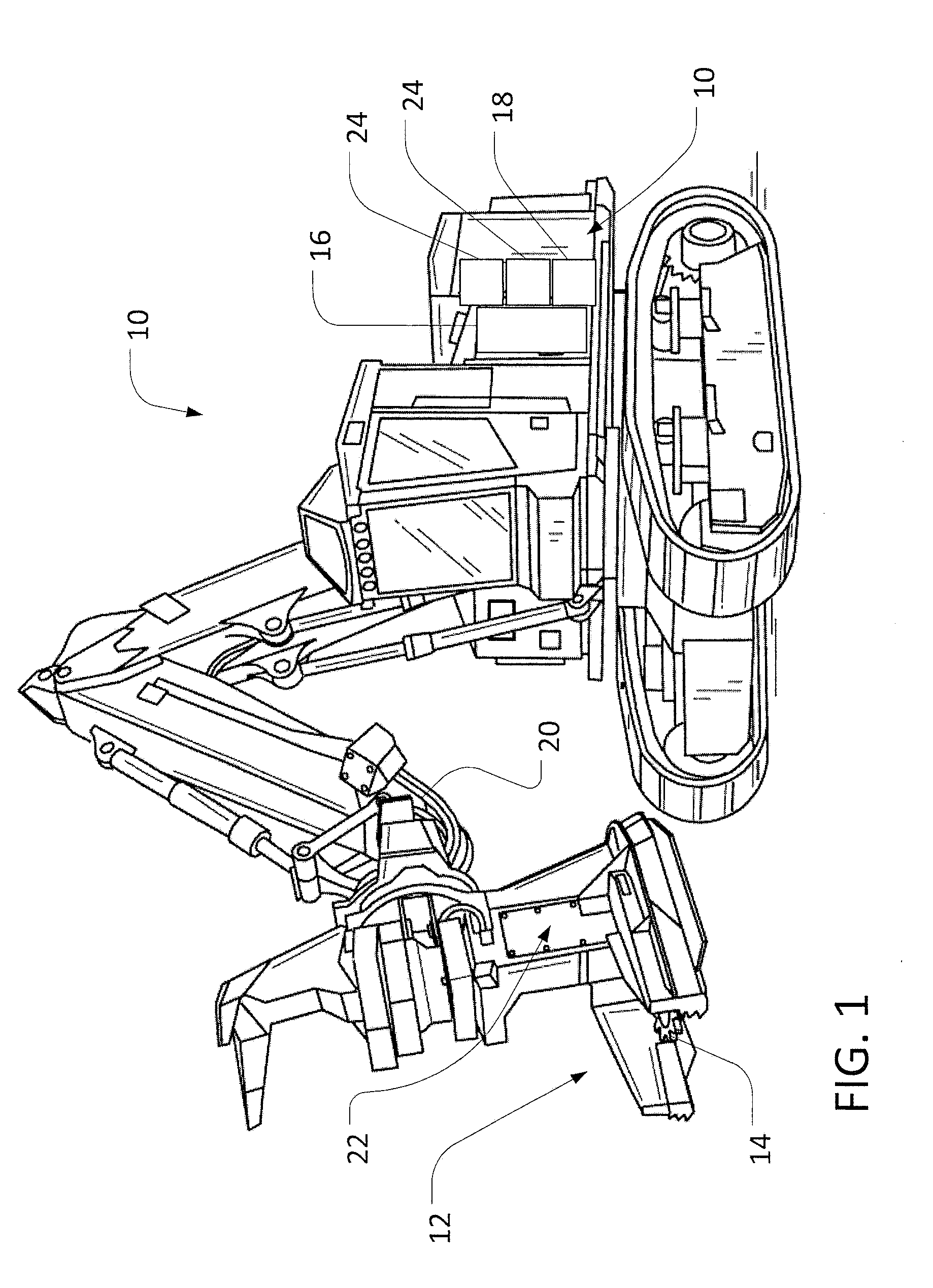
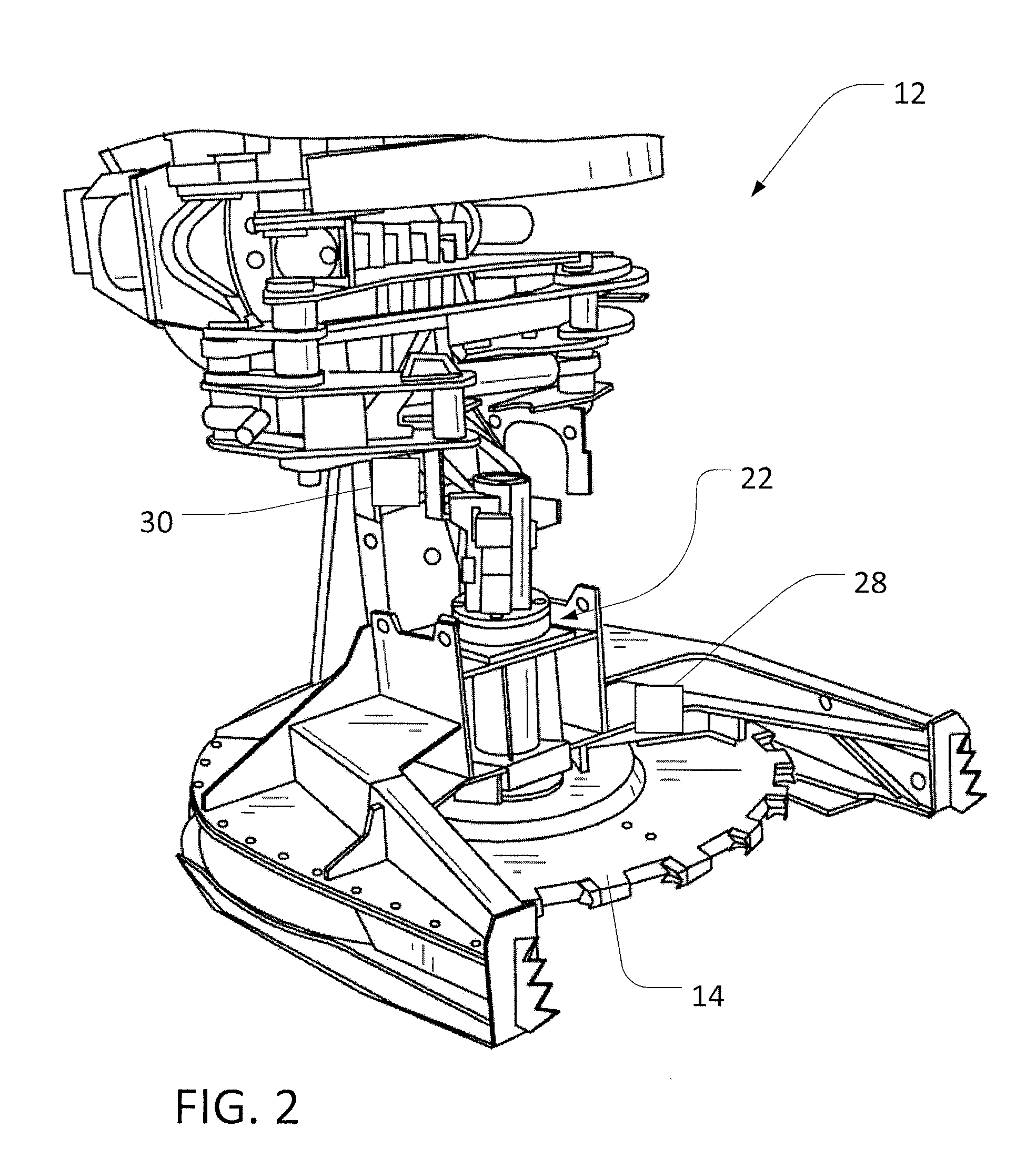
[0018]The following describes one or more example implementations of the disclosed hydraulic system for a felling saw head, as shown in the accompanying figures of the drawings described briefly above.

[0019]Various control systems described herein may be discussed as “maintaining” system parameters, such as hydraulic pressure, at a particular value. As used herein, to “maintain” a parameter (e.g., pressure) at a target value may include controlling various devices to move the parameter towards the target value upon occurrence (or detection) of a deviation from the target value. In this regard, a system may be viewed as “maintaining” a parameter at a particular target value even as the parameter deviates above or below the target. For example, where a system is “maintaining” a pressure value at a target pressure, the actual pressure value may vary among a range of values above or below the target pressure, with the system controlling appropriate devices to return the pressure value t...


PUM

PropertyMeasurementUnit
Pressureaaaaaaaaaa
Flow rateaaaaaaaaaa
Speedaaaaaaaaaa

Abstract

A hydraulic system for a felling saw head includes a hydraulic motor, operatively coupled to a saw disc of the saw head, a hydraulic variable displacement pump, operatively coupled to the hydraulic motor to supply pressurized fluid to the motor, and a controller configured to control the pump. To provide a target operating speed of the saw disc, the motor is configured to operate at a first displacement corresponding to a first flow rate of hydraulic fluid through the motor During at least a part of a saw recovery operation, the controller controls the pump to operate at a current pump displacement that results in a flow rate of hydraulic fluid through the pump that exceeds the first flow rate through the motor. Saw recovery time may be reduced without overspeeding the saw by including a metered flow control device between the pump and the motor.

Description

CROSS-REFERENCE TO RELATED APPLICATION(S)[0001]This application claims priority under 35 U.S.C. §119 to U.S. Provisional Application No. 62 / 084,806, filed Nov. 26, 2014, the disclosure of which is incorporated herein by reference.STATEMENT OF FEDERALLY SPONSORED RESEARCH OR DEVELOPMENT[0002]Not applicable.FIELD OF THE DISCLOSURE[0003]This disclosure relates to hydraulically driven saws, and in particular to the hydraulic control of tree-felling saw heads to improve saw recovery.BACKGROUND OF THE DISCLOSURE[0004]In the forestry industry wheeled and tracked feller buncher machines may be utilized to harvest standing trees. Saw heads may be mounted to the feller buncher machines, for example to a boom arm, which have one or more large saw discs with peripheral teeth. The saw head may be driven by the hydraulic system of the machine such that the saw disc is rotated. The rotating saw may thereby cut into tree trunks to fell the standing trees. The saw head may include a large grapple or...

Claims


Application Information

Patent Timeline
IPC IPC(8): F15B13/04B23D47/12F15B15/08A01G23/091
CPCF15B13/0401A01G23/091F15B2211/20546F15B15/08B23D47/12F16H61/42F16H61/47
Inventor GOEDKEN, NICHOLAS M.RASZGA, CALINRAMLER, MATTHEW J.
Owner DEERE & CO
Why Eureka
Try Eureka