
Induction hob and method for controlling an induction hob

Active Publication Date: 2016-05-26
E G O ELEKTRO GERAETEBAU GMBH
View PDF6 Cites 18 Cited by
  • Summary
  • Abstract
  • Description
  • Claims
  • Application Information

AI Technical Summary

Benefits of technology

The patent describes an induction hob with a limited number of sensor coils that can detect the presence of a pan on the hob. The sensor coils can be positioned close to the induction heating coils, allowing for a more efficient cooking zone and reducing the need for large gaps between the coils. The sensor coils can be arranged regularly or uniformly, and they can be shifted towards a central region of the hob to improve detection accuracy. The resonant frequency of the sensor coils is higher than the working frequency of the induction coils to ensure better performance and avoid interference. The induction coil is only activated when at least one of the sensor coils is covered by a pan, ensuring the presence of a pan for safe cooking.

Problems solved by technology

However, since it is desired to be able to place the pans at any desired location on such an induction hob, it may, under certain circumstances, not be sufficient, given adjacent induction heating coils, to define said heating coils, as it were, as a heating zone which is to be operated jointly and then apply said heating coils with a common identical power level on the basis of the fact that it has been detected that a pan has been placed on them.

Method used


Image

  • Induction hob and method for controlling an induction hob
  • Induction hob and method for controlling an induction hob
  • Induction hob and method for controlling an induction hob

Examples


Embodiment Construction

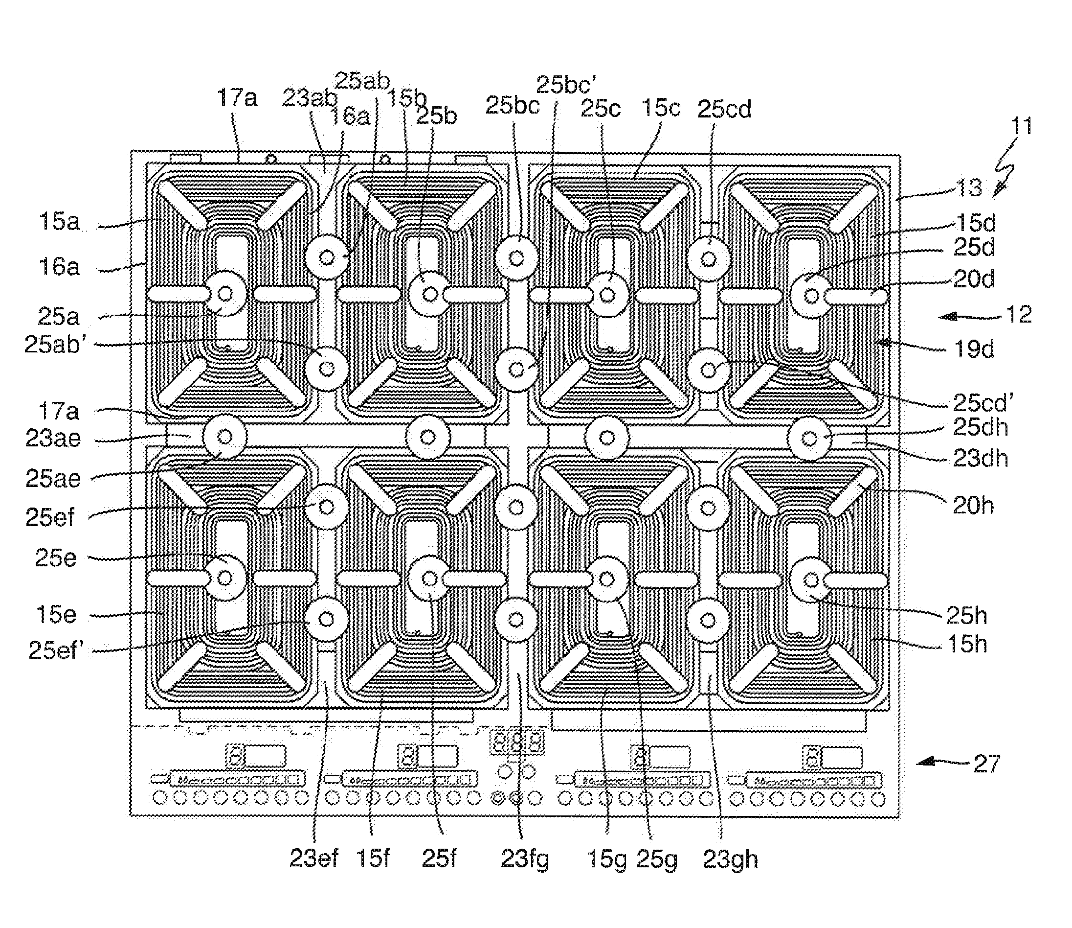
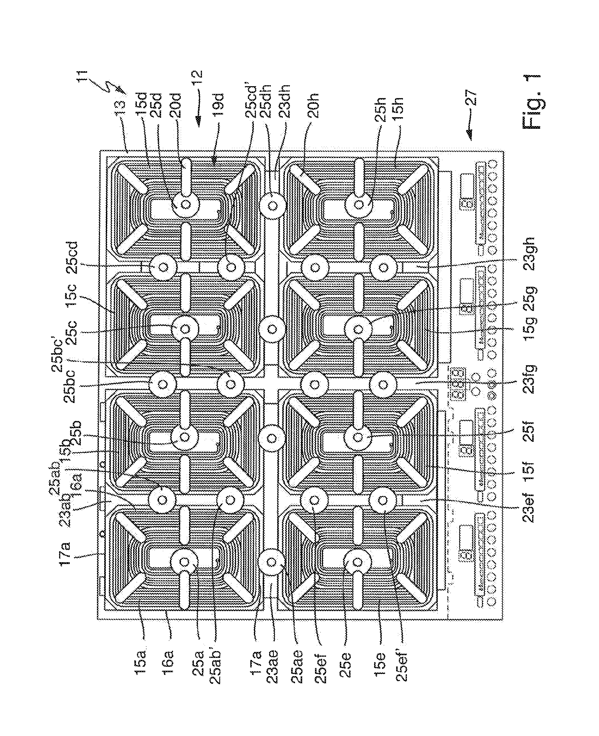
[0029]FIG. 1 shows an inventive induction hob 11 in a plan view, but with the hob plate removed, or without a hob plate, that is to say therefore a substructure 12. This substructure 12 can, as is shown, be connected to a hob plate essentially in a customary fashion. For this purpose, the substructure 12 has a carrier plate 13 which is then connected to the actual hob plate by securing means or the like.

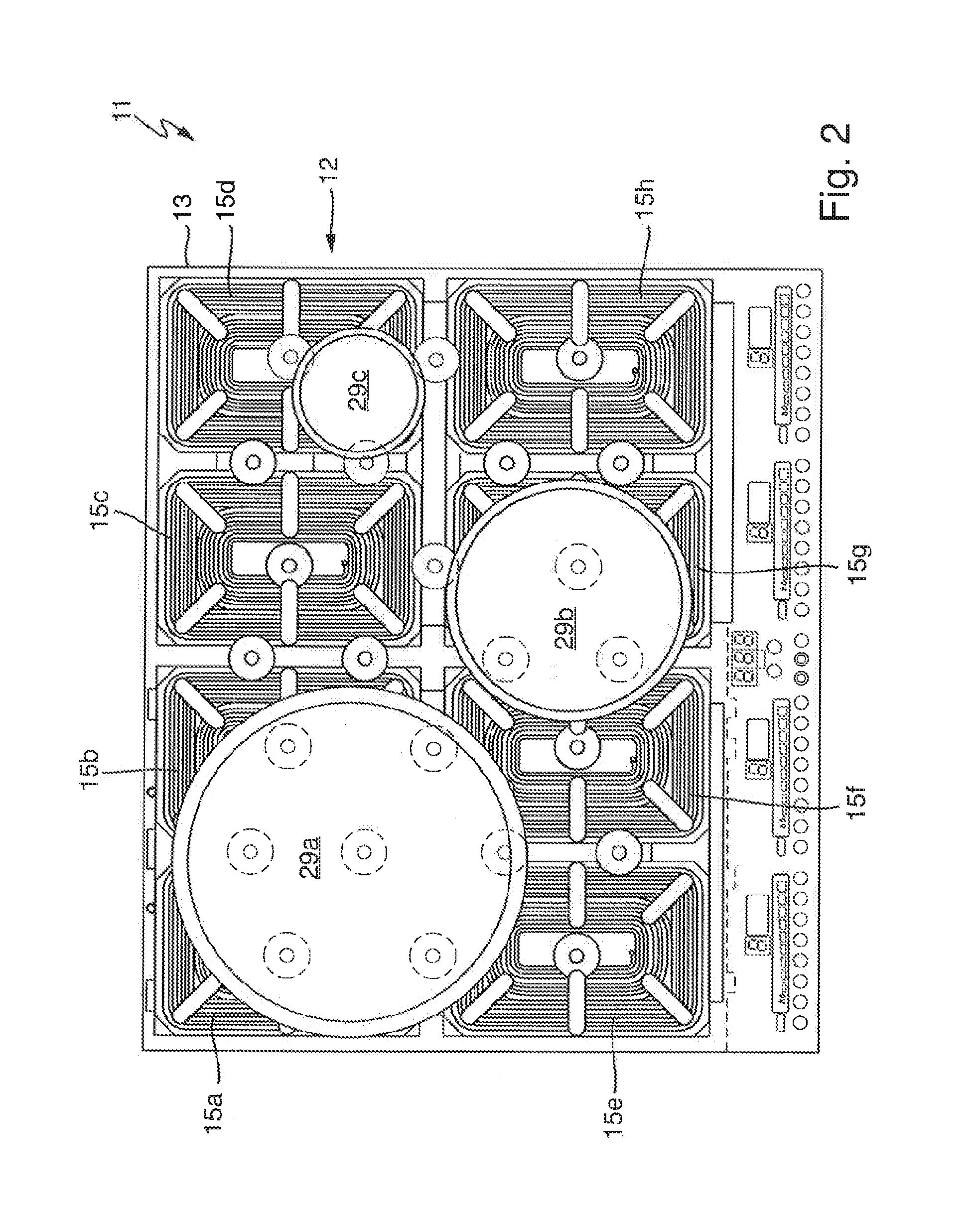
[0030]Eight essentially rectangular induction heating coils 15a to 15h are arranged on the carrier plate 13. The induction heating coils 15 are all embodied identically and oriented in the same way, as can be detected at least in their central region at the point where a respective coil turn 19a to 19h leads off downwards to the electrical connection. The induction heating coils 15 each have long sides 16a to 16h and short sides 17a to 17h. At the corners they are somewhat rounded because of the better guidance of the outer coil turns 19, since they should not be bent. Nevertheless, ...


PUM


Abstract

An induction hob has a hob plate, a plurality of induction heating coils arranged under the hob plate and a plurality of sensor coils arranged under the hob plate. The induction heating coils are rectangular, wherein at least two induction heating coils are arranged one behind the other and at least three induction heating coils are arranged one next to the other. Two adjacent induction heating coils form an adjacent region with one another in which the two induction heating coils lie with their adjacent sides. At least one sensor coil is arranged in each adjacent region, wherein precisely a single sensor coil is provided in a spacing direction from the one induction heating coil to the adjacent induction heating coil.

Description

CROSS-REFERENCE TO RELATED APPLICATIONS[0001]This application claims priority to German Application No. 10 2014 224 051.4, filed Nov. 25, 2014, the contents of which are hereby incorporated herein in its entirety by reference.TECHNOLOGICAL FIELD[0002]The invention relates to an induction hob and to a method for controlling such an induction hob.BACKGROUND[0003]In induction hobs it is technically already possible per se to use an induction heating coil to detect the presence of a pan above the induction heating coil or on a cooking zone defined by the induction heating coil, as long as the pan per se is at all suitable for inductive heating. However, in modern induction hobs, as corresponding to EP 2670211 A2, it is now possible to use a multiplicity of distributed induction heating coils to cook not only always with precisely one pan on precisely one cooking zone with precisely one induction heating coil. For this purpose, a multitude of significantly smaller induction heating coils...

Claims


Application Information

Patent Timeline
Patent Type & Authority Applications(United States)
IPC IPC(8): H05B6/36H05B6/06
CPCH05B6/36H05B2213/05H05B6/065H05B6/062H05B2213/03H05B2213/07
Inventor LOMP, STEPHANERUPP, MICHAELDALAKER, TIMOSTOEFFLER, MICHAELFRIEDRICH, HARTMUTEGENTER, CHRISTIANMOHR, WOLFGANGEBERLE, MICHAELGRUNOW, THORSTEN
Owner E G O ELEKTRO GERAETEBAU GMBH
Learn More