Liquid ejection apparatus and method for manufacturing liquid ejection apparatus

Active Publication Date: 2016-06-02
BROTHER KOGYO KK
View PDF1 Cites 3 Cited by
  • Summary
  • Abstract
  • Description
  • Claims
  • Application Information

AI Technical Summary

Benefits of technology

[0011](3) In order to lower the electric resistance, it is desirable that the trace has a certain thickness or more. However, as is the case of Japanese Unexamined Patent Application Publication No. 2006-123518, when a configuration in which the trace with a certain thickness is connected on the upper electrode is employed, unevenness occurs at the portion where the upper electrode and the trace overlap each other. Accordingly, when forming the protective film after the trace has been formed, the material forming the protective film does not easily deposit in the vicinity of the uneven portion and the thickness of the protective film becomes partially thin. Accordingly, it is desirable that the protective film is deposited on a surface that is in a state in which no trace is formed and that is as flat as possible.
[0012]As described above, various problems may be encountered in the configuration of Japanese Unexamined Patent Application Publication No. 2006-123518. Accordingly, as illustrated in FIG. 14, it is preferable that, after an upper electrode 133 is formed on a piezoelectric porti

Problems solved by technology

In such a case, problems described below may disadvantageously occur.
Accordingly, when patterning the trace by etching, the piezoelectric portion and the upper electrode may be scraped away and the film thicknesses may disadvantageously become thin.
Furthermore, with hydrogen and the like that is contained in the etching solution for performing etching, the piezoelectric portion that is an oxide may be disadvantageously damaged such as being reduced.
The oxygen defect may disadvantageously cause

Method used


Image

  • Liquid ejection apparatus and method for manufacturing liquid ejection apparatus
  • Liquid ejection apparatus and method for manufacturing liquid ejection apparatus
  • Liquid ejection apparatus and method for manufacturing liquid ejection apparatus

Examples


Example

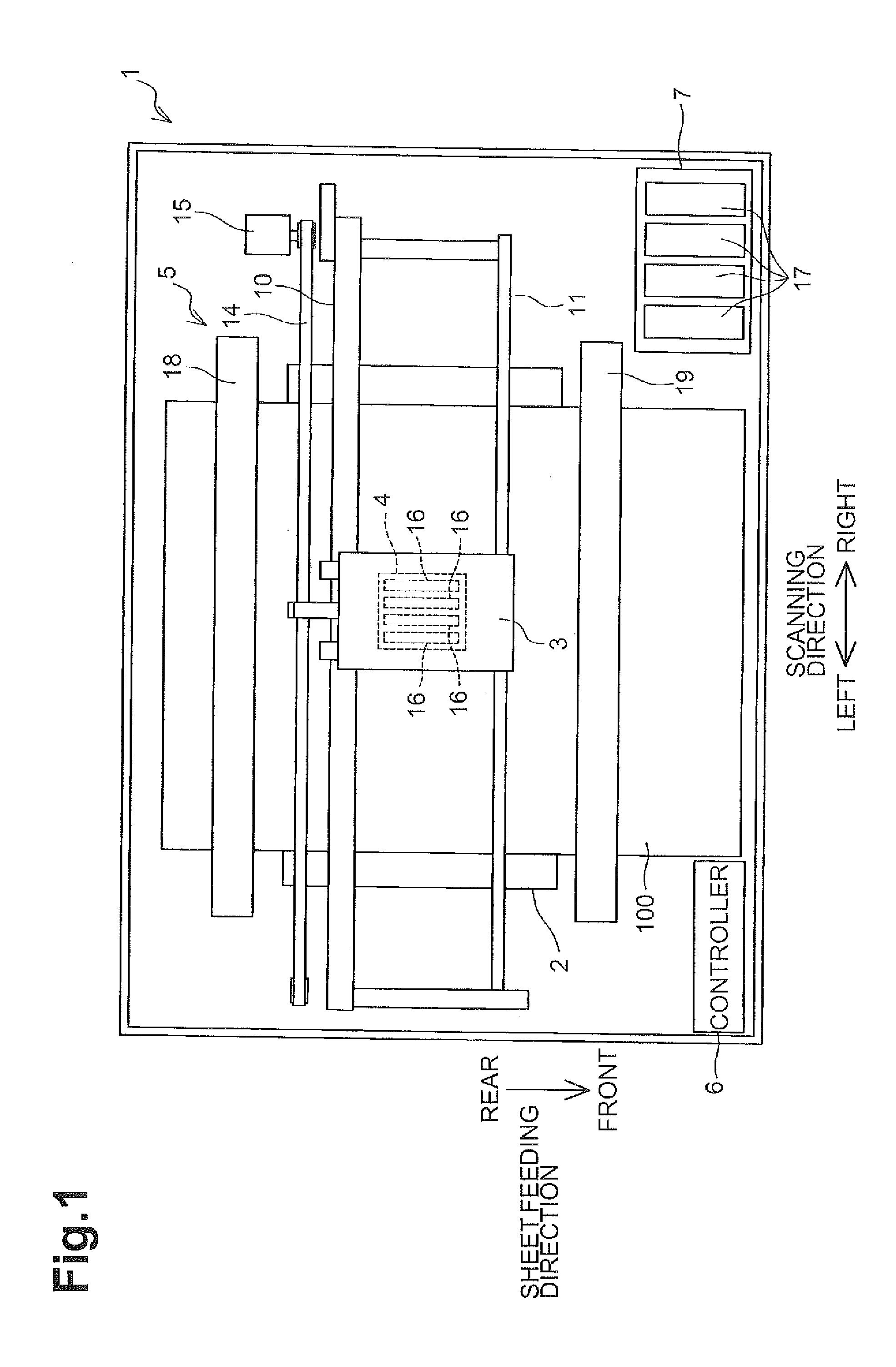
[0030]An exemplary embodiment of the present disclosure will be described next. FIG. 1 is a schematic plan view of a printer according to the present exemplary embodiment. Referring to FIG. 1, a schematic configuration of an inkjet printer 1 will be described first. Note that front, rear, left, and right directions illustrated in FIG. 1 defines the “front”, “rear”, “left”, and “right” of the printer, respectively. Furthermore, this side of the paper is defined as the “up” side and that side of the paper is defined as the “down” side. Hereinafter, the description will be given using, as required, each of the directional terms such as front, rear, left, right, up, and down.

Schematic Configuration of Printer

[0031]As illustrated in FIG. 1, the inkjet printer 1 includes a platen 2, a carriage 3, an inkjet head 4, a transport mechanism 5, and a controller 6.

[0032]A piece of recording sheet 100 (e.g., paper) that is a recording medium is placed on an upper surface of the platen 2. The carr...


PUM


Abstract

A liquid ejection apparatus and method of manufacture are disclosed. One apparatus includes a piezoelectric element corresponding to a pressure chamber in a channel substrate, a trace corresponding to the piezoelectric element. The piezoelectric element includes a piezoelectric layer, a first electrode, a second electrode disposed on a surface of the piezoelectric layer on a side opposite the channel substrate, and a protective film covering the piezoelectric layer and the second electrode. The second electrode includes a lead-out portion that extends to an area over the channel substrate where the piezoelectric layer is not disposed, and a contact portion that is provided in the lead-out portion and that is exposed from the protective film in the area. The trace is connected to the second electrode at the exposed contact portion.

Description

CROSS-REFERENCE TO RELATED APPLICATION[0001]This application claims priority from Japanese Patent Application No. 2014-242978 filed on Dec. 1, 2014, which is incorporated herein by reference in its entirety.BACKGROUND[0002]1. Technical Field[0003]The present disclosure relates to a liquid ejection apparatus that ejects a liquid and a method for manufacturing the liquid ejection apparatus.[0004]2. Description of the Related Art[0005]Japanese Unexamined Patent Application Publication No. 2006-123518 discloses, as a liquid ejection apparatus, an inkjet head that records an image and the like by discharging ink onto a recording medium. The inkjet head of Japanese Unexamined Patent Application Publication No. 2006-123518 includes a channel defining substrate in which a plurality of pressure chambers are formed and a piezoelectric actuator provided in a diaphragm of the channel defining substrate that covers the plurality of pressure chambers.[0006]The piezoelectric actuator includes a pl...

Claims


Application Information

Patent Timeline
IPC IPC(8): B41J2/14B41J2/16
CPCB41J2/14233B41J2002/14241B41J2/1626B41J2/161B41J2/1628B41J2/1629B41J2/1631
Inventor TANAKA, TAIKI
Owner BROTHER KOGYO KK
Why Eureka
Try Eureka