System for preventing the urea crystal formation within an exhaust gas after treatment system

a technology of exhaust gas and urea crystals, which is applied in the field of after treatment systems, can solve the problems of insufficient gas energy exchange and unacceptable behavior

Active Publication Date: 2016-06-02
FPT MOTORENFORSCHUNG
View PDF0 Cites 10 Cited by
  • Summary
  • Abstract
  • Description
  • Claims
  • Application Information

AI Technical Summary

Benefits of technology

[0015]The main advantage of the present invention is that the electric power required for avoiding the crystal formation is several times less than those systems that aim to heat the exhaust gasses and, only indirectly, the urea mixture.
[0016]These and further objects are achieved by means of an apparatus and method as described in the attached claims, which form an integral part of the present description.

Problems solved by technology

However at lower exhaust gas temperature and velocity there is often insufficient energy exchange from the gas to avoid liquid wall wetting and formation of solid deposits.
This is an unacceptable behavior due to wrong NH3 dosing to the SCR system and / or increased back pressure due to deposits.

Method used


Image

  • System for preventing the urea crystal formation within an exhaust gas after treatment system
  • System for preventing the urea crystal formation within an exhaust gas after treatment system
  • System for preventing the urea crystal formation within an exhaust gas after treatment system

Examples


Embodiment Construction

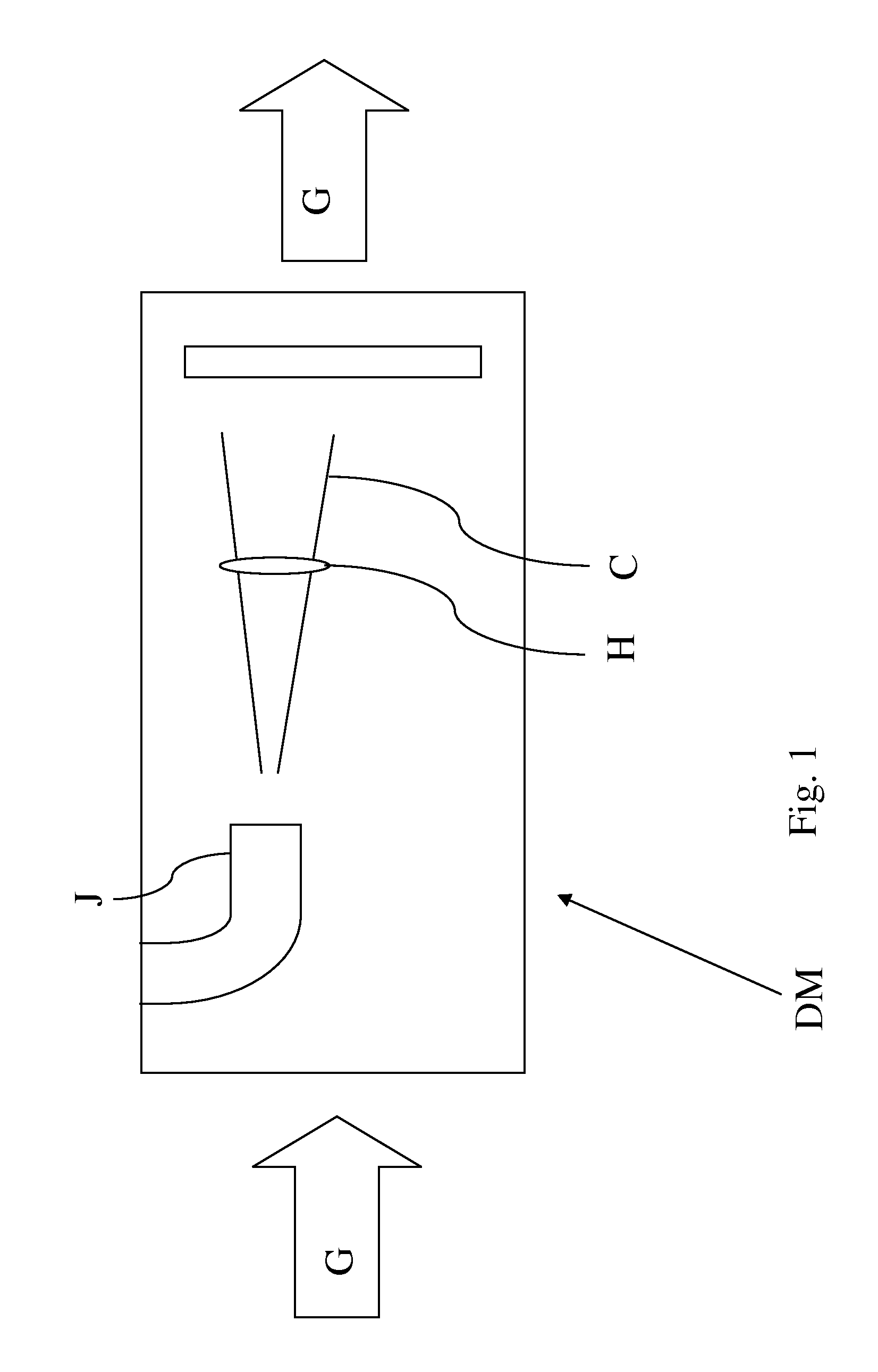
[0023]On FIG. 1 is shown a dosing module DM, and in particular a side view of a portion of an exhaust pipe defining the ATS.

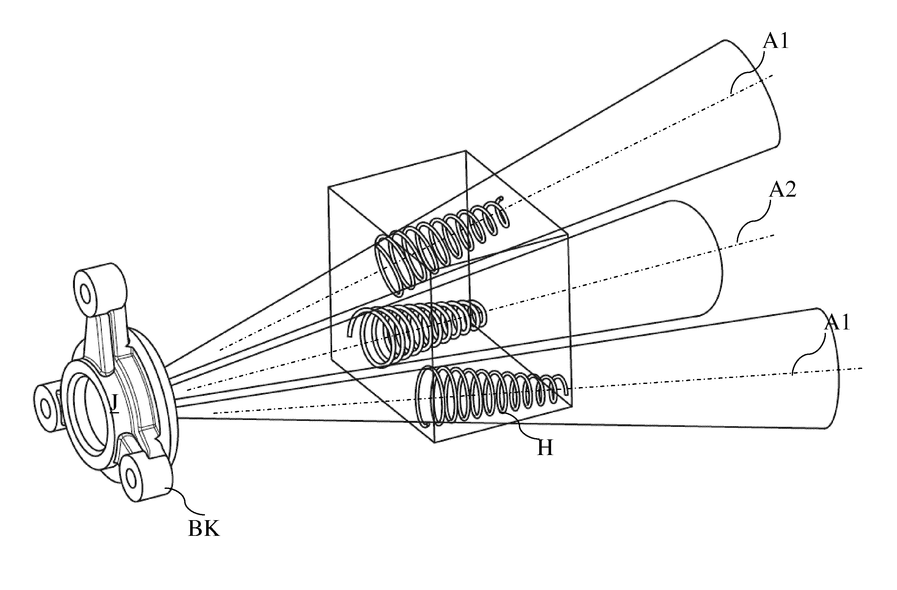
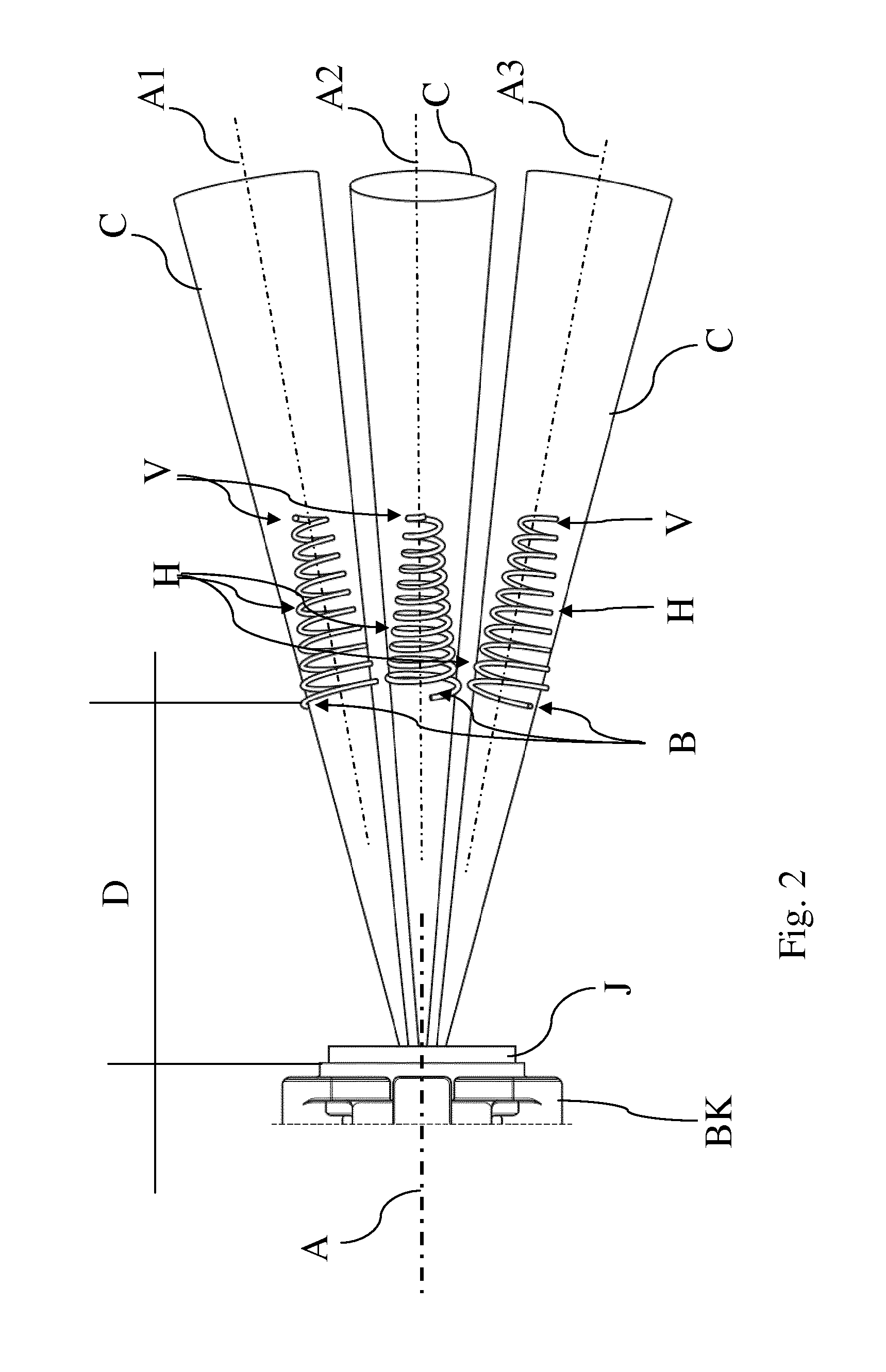
[0024]An injector J—also called dosing means—produce a spray of urea mixture, forming at least one spray cone C.

[0025]According to the present invention an electric heating element H—or simply “heater”—is arranged in a portion P of said pipe, downstream of the dosing module DM, with respect to the exhaust gas flow indicated by the thick arrow on the left of the sheet of FIG. 1, so as to be crossed by the spray cone C.

[0026]This means that the heating element does not have a continuous surface, facing the injector nozzle, but has a through hollow body, comprising one or more paths, that can be easily crossed either by the urea spray, and / or by the exhaust gas G.

[0027]Optionally, a mixer M can be present downstream of the heater H.

[0028]The electrical heating element is suitable to be connected to an electrical source, for example, through the vehicular electrica...


PUM


Abstract

System for preventing the urea crystal formation within the ATS, the exhaust ATS comprising a dosing module having dosage means for producing a spray of urea-based reducing agent defining a spray cone downstream of the dosage means, the device comprising an electric heating element, suitable to be connected to an electrical energy source, arranged in order to operatively fall within the spray cone.

Description

CROSS-REFERENCE TO RELATED APPLICATIONS[0001]The present application claims priority to PCT International Application No. PCT / EP2014 / 065504 filed on Jul. 18, 2014, which application claims priority to European Patent Application No. 13177048.9 filed Jul. 18, 2013, the entirety of the disclosures of which are expressly incorporated herein by reference.STATEMENT RE: FEDERALLY SPONSORED RESEARCH / DEVELOPMENT[0002]Not ApplicableFIELD OF THE INVENTION[0003]The present invention relates to the fields of the After Treatment Systems, and in particular to the field of systems for preventing the urea crystal formation within the ATS.DESCRIPTION OF THE PRIOR ART[0004]Aftertreatment systems are commonly used to reduce emissions. The NOx reduction is mainly realized by a selective catalytic reduction (SCR) system. The required Ammonia (NH3) for the reduction of the NOx is usual injected as a liquid with dissolved UREA, commonly AdBlue(r) or DEF (Diesel Exhaust Fluid) with water with 32.5% of urea...

Claims


Application Information

Patent Timeline
Patent Type & Authority Applications(United States)
IPC IPC(8): F01N3/20
CPCF01N3/208F01N2610/10F01N2610/1453F01N2610/02F01N3/2066F01N2610/102Y02A50/20Y02T10/12
Inventor ASSALVE, DANIELCAMPBELL, JOHNFESSLER, HARALDSCHLEGEL, RETO
Owner FPT MOTORENFORSCHUNG
Why Eureka
Try Eureka