
Optical structure with ridges arranged at the same and method for producing the same

a technology of optical structure and ridges, applied in the direction of optics, contact member assembly/disassembly, mountings, etc., can solve the problems of individual parts and inability to produce in wafer level technology

Active Publication Date: 2016-06-02
FRAUNHOFER GESELLSCHAFT ZUR FOERDERUNG DER ANGEWANDTEN FORSCHUNG EV
View PDF3 Cites 96 Cited by
  • Summary
  • Abstract
  • Description
  • Claims
  • Application Information

AI Technical Summary

Benefits of technology

The optical apparatus described in this patent can self-regulate its optical characteristics by using ridges that allow the optical structure to move in relation to a reference plane. This compensates for variations in optical characteristics caused by temperature changes. The ridges are made in a single-layered way, which simplifies production. The apparatus also includes a mechanism that makes it easier to maintain the initial position of the optical structure after adjustment. Additionally, the patent describes a concept for optical apparatuses that use miniaturized actuators and wafer level technology, which can lead to smaller construction sizes and lower production costs. Overall, the patent describes a technique to overcome limitations in optical apparatuses and lead to improved performance.

Problems solved by technology

However, these methods necessitate active adjustment of the focal length of the optical system.
The same consist of many individual parts and cannot be produced in wafer level technology.

Method used


Image

  • Optical structure with ridges arranged at the same and method for producing the same
  • Optical structure with ridges arranged at the same and method for producing the same
  • Optical structure with ridges arranged at the same and method for producing the same

Examples


Embodiment Construction

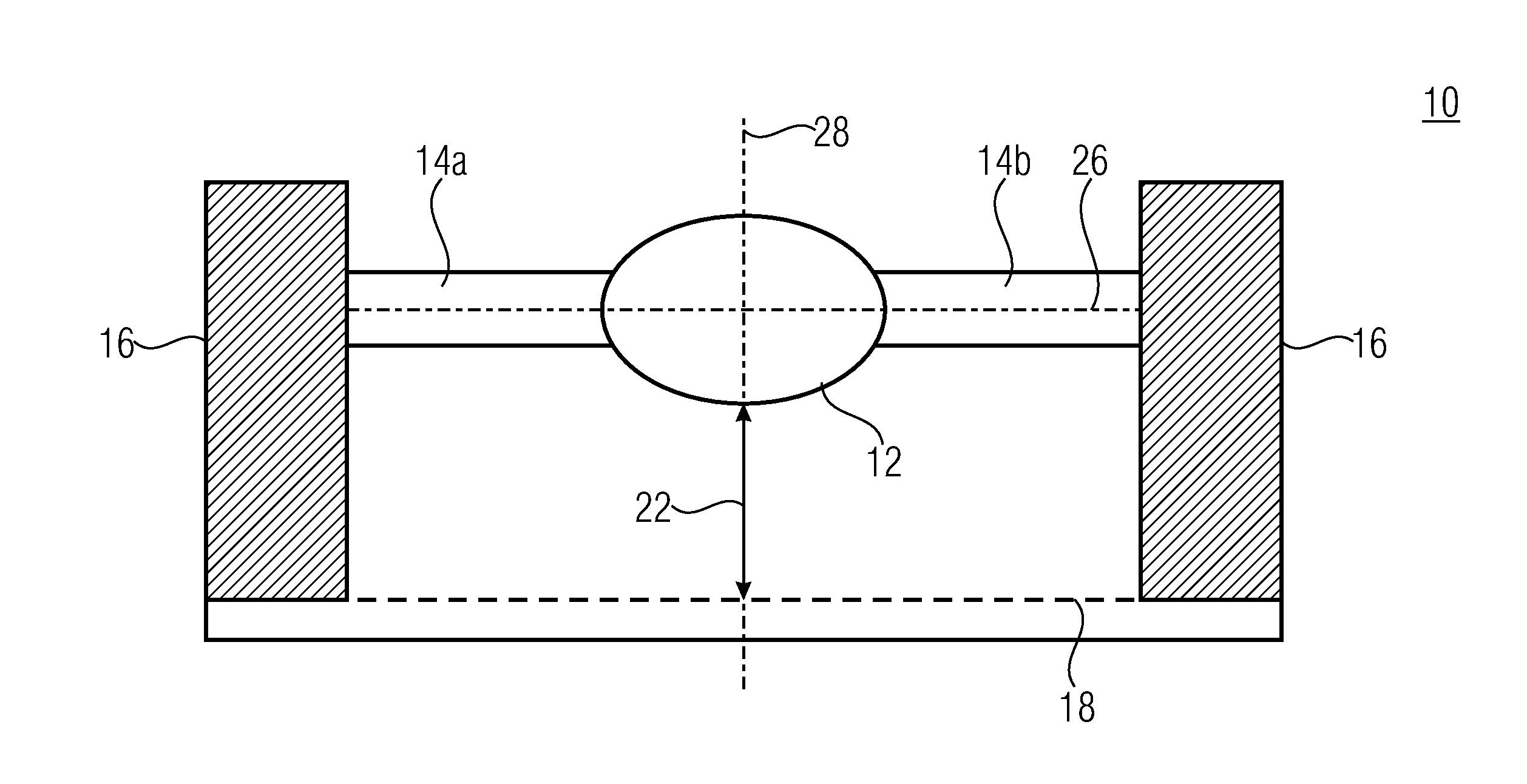
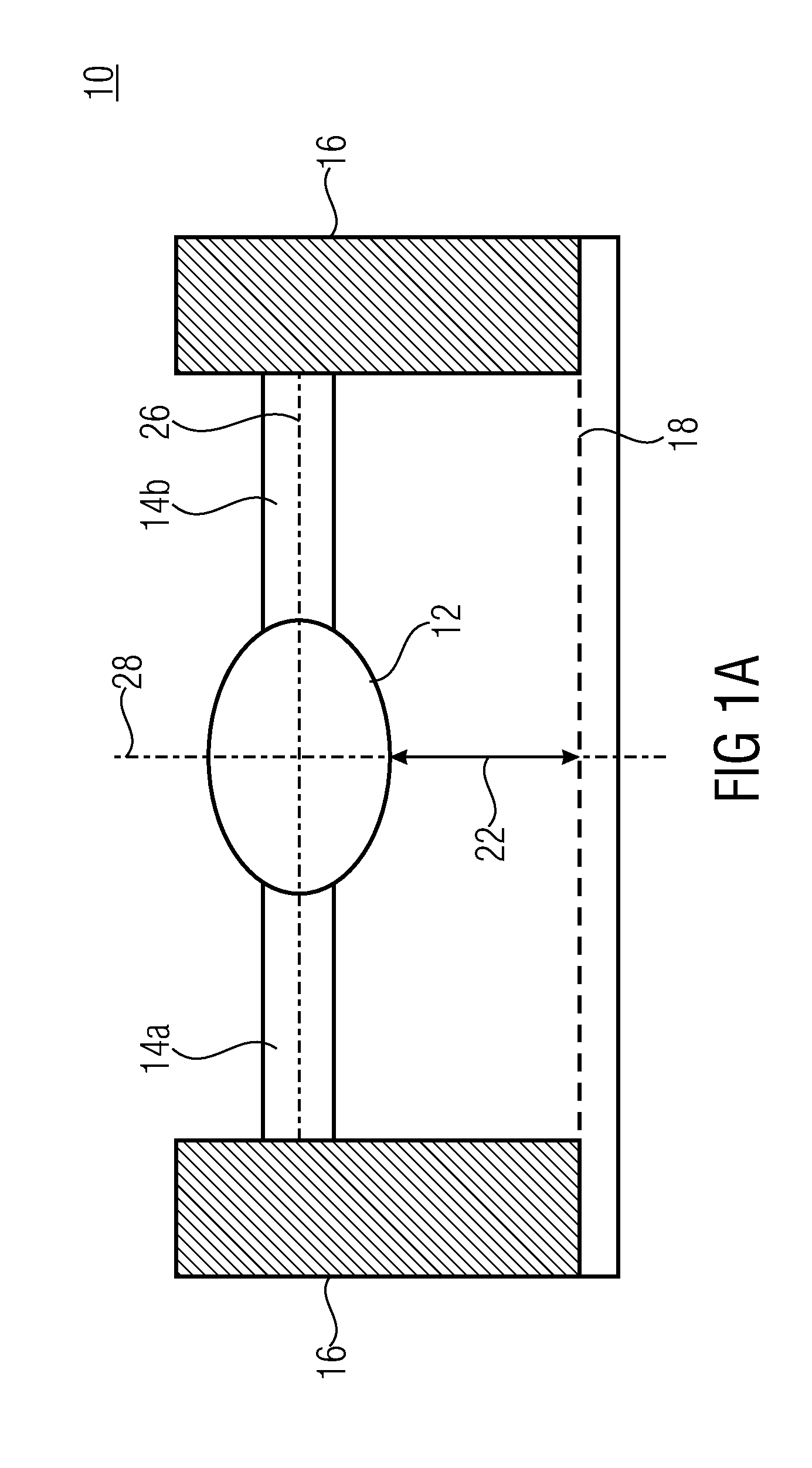
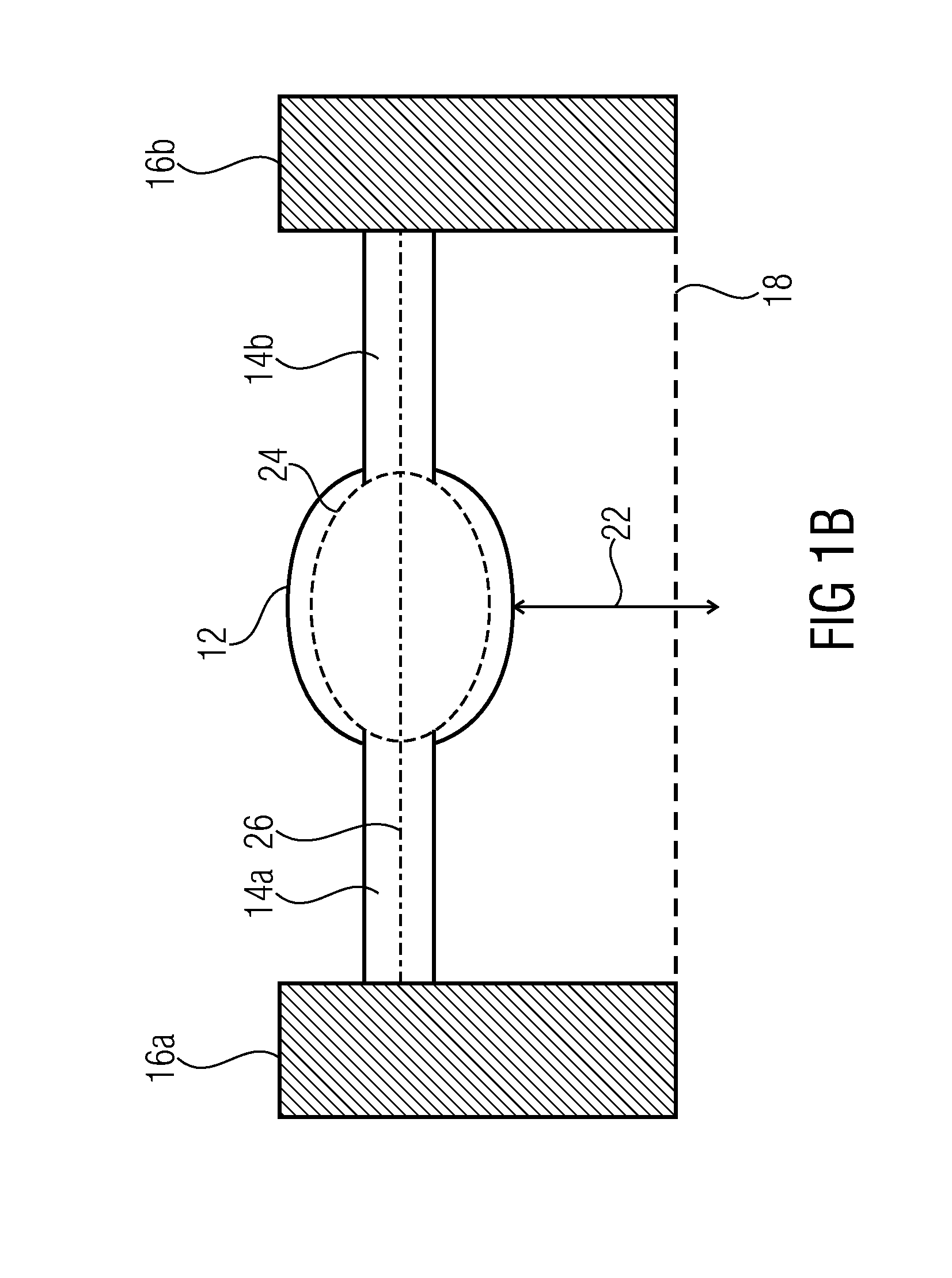
[0168]FIG. 1a shows a cross-sectional view of an apparatus 10 according to an embodiment of the invention. The apparatus includes a lens 12 mounted on a supporting structure 16, for example a frame, via two ridges 14a and 14b and arranged at a distance 22 to a reference plane18 shown schematically in FIG. 1. The lens 12 and the ridges 14a and 14b are arranged in a common position plane 26. The reference plane 18 can, for example, represent an image plane where the image sensor comprised by the apparatus 10 is arranged. The distance 22 is selected according to the focal length of the lens 12. The ridges 14 are structured in a single-layered manner of a material including a greater coefficient of thermal expansion than the supporting structure 16. In case of a temperature increase, the ridges consequently expand particularly along the direction from the supporting structure 16 towards the lens 12 more than the supporting structure and can hence effect a deflection of the lens from the...


PUM


Abstract

An apparatus having an optical structure, ridges and an electrostatic actuator with a cantilever electrode is described, wherein the ridges connect the optical structure to a supporting structure and the electrostatic drive is implemented to deflect the optical structure.

Description

CROSS-REFERENCE TO RELATED APPLICATIONS[0001]This application is a continuation of copending International Application No. PCT / EP2014 / 060726, filed May 23, 2014, which is incorporated herein by reference in its entirety, and additionally claims priority from German Application No. 10 2013 209 829.4, filed May 27, 2013, which is also incorporated herein by reference in its entirety.BACKGROUND OF THE INVENTION[0002]The present invention relates to an apparatus having an optical structure and ridges connecting the optical structure to a supporting structure, wherein the optical structure is able to perform a movement with regard to a reference plane, and the invention also describes possible adjustments for the apparatus.[0003]Optical structures made of curable material, as are known, for example, from DE 102009055080 A1, change their characteristics with varying environmental temperatures. Thus, a polymer lens changes its extension with varying temperature, such that the refractive in...

Claims


Application Information

Patent Timeline
IPC IPC(8): G02B7/02G02B7/18G02B7/00
CPCG02B7/028G02B7/025G02B7/181G02B7/008G02B26/0841
Inventor WIPPERMANN, FRANKREIMANN, ANDREASLANGE, NICOLASBRAEUER, ANDREAS
Owner FRAUNHOFER GESELLSCHAFT ZUR FOERDERUNG DER ANGEWANDTEN FORSCHUNG EV
Learn More